Does Cable Length Affect Sound Quality? Limits for Balanced and Instrument Runs
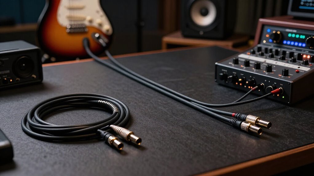
Cable length can affect sound quality because capacitance, resistance, and interference rise with distance. Keep passive, unbalanced instrument cables under 15 to 20 feet; 25 feet may work but can lose treble or collect noise.
You can usually run balanced XLR or TRS line-level signals 50 to 100 feet, often farther, when both devices are truly balanced.
Use low-impedance outputs, high-impedance inputs, intact shields, and proper speaker cable. The details clarify why source impedance and wiring determine your limit.
Balanced Lines Handle Longer Runs
Balanced lines handle longer cable runs by sending opposite-polarity versions of the same audio signal through two conductors. Each conductor carries an inverted relationship to the other, while a separate ground provides shielding and reference. At the input, differential circuitry compares both conductors and rejects interference that couples equally into each one.
You consequently retain a cleaner signal across distances where external electromagnetic fields might otherwise intrude. Balanced XLR and TRS connections commonly support 50 to 100 foot (15 to 30 meter) runs, and properly designed balanced equipment can often extend beyond 100 feet without perceptible degradation. However, you need balanced outputs and inputs; a balanced cable attached to unbalanced equipment won’t deliver equivalent common-mode noise rejection. Use balanced routing near power equipment or other nearby interference sources.
Capacitance Causes High-Frequency Loss
Even when interference isn’t the limiting factor, cable capacitance can shape the signal’s frequency response. Capacitance describes a cable’s ability to store electrical charge. As capacitance increases, it interacts with the source and load impedances to attenuate upper frequencies, effectively forming a low-pass response. Because capacitance accumulates per foot, a longer cable usually presents more total capacitance than a shorter one.
You’ll notice this concern most often with unbalanced instrument connections, where cable capacitance can audibly alter treble response. The degree of loss doesn’t follow length alone: it depends on the cable’s capacitance rating, total run length, and the specific application. A low-capacitance cable reduces the effect, but you should still use the shortest practical run to preserve high-frequency content at your instrument output.
100-Foot Stage Snake Example
A 100-foot stage snake shows why balanced connections suit long audio runs: XLR mic lines can carry low-level signals from the stage to a mixer while rejecting much of the hum and interference collected along the route. That performance depends on a balanced source, snake, and mixer input; cable geometry alone can’t convert an unbalanced output. Verify connector wiring, equipment documentation, and compatible pinouts before deployment.
| Check | Requirement |
|---|---|
| Signal path | Balanced at both ends |
| Instrument lead | Keep under 15 to 20 feet |
You protect weak microphone-level signals by using the snake for the full run. In contrast, don’t extend an unbalanced instrument cable across the stage: its higher susceptibility to induced noise and capacitive signal loss makes short leads preferable when you can use balanced paths.
Instrument vs. Line-Level Cables
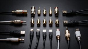
You must account for signal level and impedance: your guitar or bass typically uses a high-impedance, unbalanced TS instrument cable, which you should keep near 15 to 20 feet or less. For interfaces, mixers, and monitors, use balanced TRS or XLR line-level connections to reject common-mode noise across runs of 50 to 100 feet. Match each cable to the equipment’s actual I/O, because a balanced cable can’t convert an unbalanced instrument output into a balanced signal.
Signal Levels and Impedance
Signal level and impedance largely determine how much cable length affects sound quality. Your instrument output produces a relatively low-level, high-impedance signal, so cable capacitance interacts with the source impedance to form a low-pass network. As capacitance rises, high-frequency content attenuates more readily, while external electromagnetic interference becomes more audible.
Line-level outputs deliver greater voltage and usually lower source impedance, improving noise margin and reducing capacitance-related tonal change. With balanced line-level equipment, the receiving input compares opposite-polarity conductors and rejects noise coupled equally onto both lines. The separate ground provides shielding and reference, rather than carrying the audio return alone. Still, you should consider total capacitance, output impedance, input impedance, and device specifications when choosing the shortest practical connection for your setup and routing.
Instrument Cable Length Limits
For most passive instruments, keep an unbalanced TS cable under about 15 to 20 feet (4 to 6 meters) to limit capacitance-related high-frequency loss and susceptibility to electromagnetic interference. Passive pickups produce a low-level, high-impedance signal, so cable capacitance forms a low-pass network that can soften treble as length increases. Longer unbalanced runs also expose the conductor to hum, RF, and other induced noise. Use the shortest practical cable between your instrument and first buffer, pedal, or input.
In a controlled environment with low interference, you may obtain acceptable results at roughly 25 to 30 feet, but cable capacitance, shielding, pickup type, and nearby power sources determine the outcome. Don’t assume a longer cable merely reduces level; it can audibly alter your instrument’s frequency response and noise floor noticeably.
Line-Level Run Considerations
Instrument and line-level connections impose different length limits because their voltage, impedance, and noise-rejection methods differ. Instrument leads are usually unbalanced TS cables carrying relatively low-level, high-impedance signals, so you should keep them below 15 to 20 feet (4 to 6 meters) where possible, particularly near power supplies, lighting, or other interference sources. Line-level outputs provide stronger signals and may use balanced XLR or TRS wiring.
When both your source and destination implement balanced operation, a 50 to 100-foot (15 to 30-meter) run commonly rejects induced noise effectively. A balanced cable by itself can’t create balanced signaling; both devices must support it. Unbalanced line-level links remain susceptible to interference, so keep them short. In every setup, use the shortest practical cable and verify each device’s connector wiring and compatibility before installation carefully.
Source and Load Impedance
Your source impedance determines how strongly cable capacitance can attenuate high frequencies, especially as cable length increases. You’ll minimize these effects when a low-impedance source drives a high-impedance input, whereas a high source impedance or low load impedance can reduce level and treble. For reliable signal transfer, match cable choice and length to the source and load characteristics rather than assuming every connection behaves alike.
Source Impedance Matters
Source impedance determines how strongly cable capacitance alters a signal: as cable length rises, a high-impedance output such as a passive guitar pickup can form a low-pass filter with the cable and audibly reduce treble. Capacitance rises with length, lowering the filter’s cutoff frequency when source resistance stays high. You may hear a softer, less defined top end before obvious level loss.
Passive pickups, piezo elements, and some vintage outputs need attention because their impedance varies with frequency and control settings. By contrast, a low-impedance buffered, active, or line-level output drives identical capacitance effectively, letting you use longer runs with far less high-frequency change. Check source’s output impedance and cable capacitance, and test response. Keep instrument cables short; use a buffer for longer routing.
Load Impedance Effects
Cable length affects level and tonal balance through the impedance relationship between the output, cable, and receiving input. If you connect a high-impedance source to a relatively low-impedance input, the input draws more current and cable resistance contributes more appreciably to level loss. This becomes increasingly relevant as run length rises. Line-level outputs normally feed inputs with substantially higher impedance, so practical cable lengths produce little attenuation from resistance.
However, cable capacitance remains significant because it combines with source impedance to create a low-pass response. A low-impedance output drives that capacitance effectively and preserves high frequencies over longer compatible runs. Guitar pickups, by contrast, often present high impedance; long, high-capacitance instrument cables can audibly soften treble. A buffer lowers driving impedance and limits roll-off.
Matching for Signal Transfer
Proper signal transfer depends on impedance bridging, not matching: the driving device should present a low output impedance, while the receiving input should present a much higher impedance. This relationship lets voltage reach the input directly rather than dropping across the source. Line-level equipment follows this design, so you don’t select cable impedance to equal source and load values.
However, cable capacitance still interacts with source impedance. High-impedance instrument pickups, especially passive guitar pickups, can lose treble as cable length and capacitance increase. Connecting them to a low-impedance input can load the pickup further; a buffer preserves the response by providing a low-impedance drive. Speaker circuits differ: your amplifier needs low output impedance relative to the speaker, but cable resistance reduces level and weakens damping.
Home-Studio Monitor Connections
For home-studio monitors, use balanced XLR or TRS connections from your interface or mixer whenever both devices support them. Balanced lines send opposite-polarity versions of the same mono signal; the monitor input rejects noise induced equally on each conductor. This matters when your run is longer or crosses areas near power equipment. Keep it as short as practical while leaving enough slack for placement.
| Connection check | Why it matters |
|---|---|
| Balanced output to balanced input | Preserves common-mode noise rejection. |
| TRS wiring verified | TRS may be balanced mono or unbalanced stereo. |
Confirm device manuals specify connectors and balanced pinout. A unbalanced cable can work, but it is susceptible to hum, particularly when you route it parallel to mains wiring. Separate signal and power paths where possible.
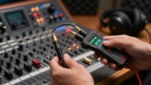
Damaged Shields Defeat Noise Rejection
Balanced wiring can reject noise only when the cable’s shield and conductors remain intact. Your balanced input subtracts opposite-polarity signal copies, canceling interference that both conductors pick up equally. The shield reduces the amount of external electromagnetic energy reaching those conductors. If it is cut, poorly terminated, or disconnected, hum, buzz, and radio-frequency contamination can enter more readily. A shield failure may also interrupt the grounding path, creating noise that balanced circuitry cannot remove.
Inspect cable jackets, strain-relief points, and connector shells. Test suspect cables after bending, crushing, or intermittent faults. Replace a cable with a compromised shield instead of expecting balanced connections to compensate. Keep damaged or unverified leads away from long routes and noisy locations, where interference is likely to become audible.
Using Mic Cable for Speakers
Cable condition matters, but cable type matters just as much: don’t use a typical microphone cable between an amplifier’s speaker output and a passive speaker. Mic cable carries balanced, low-level audio, not amplified speaker power. Its thin conductors raise series resistance, wasting power, reducing damping and output, and potentially overheating under sustained load.
- Use purpose-built speaker cable with conductor size matched to the run.
- Higher current demands low resistance, especially at elevated power.
- You may use mic cable for a powered speaker’s balanced line-level input.
- Verify manuals and connector wiring; XLR or TRS plugs don’t prove speaker-level suitability.
Select cable gauge according to the manufacturer’s guidance and installation distance. Never infer electrical capability from connector gender, shell style, or familiar stage-cable appearance alone, ever.
Compare 10- and 25-Foot Runs
A 10-foot unbalanced instrument cable usually provides a practical short run, whereas 25 feet exceeds the common 15 to 20-foot guideline and increases exposure to capacitance, resistance, and external interference. You’ll notice the difference most readily with low-level pickups, in electrically noisy rooms, or when the longer cable parallels AC power lines.
Greater capacitance can soften high-frequency response, while added resistance contributes signal loss; interference may present as hum, buzz, or radio-frequency contamination. Route the cable away from power wiring whenever possible. If your equipment supports balanced I/O, a 25-foot balanced connection rejects common-mode noise better than an unbalanced instrument lead. When you need 25 feet from an instrument, test the rig at the venue. If noise persists, use a shorter lead, DI box, or wireless system.
Conclusion
Your cable length affects sound only when impedance, capacitance, shielding, and signal level interact unfavorably. You can run balanced, low-impedance lines hundreds of feet when shields and connectors remain intact. Keep high-impedance instrument cables short because capacitance rolls off treble.
For monitors, use balanced line cables; for speakers, use proper low-resistance speaker cable; don’t use mic cable. Comparing 10- and 25-foot runs usually reveals no audible change if both cables suit the source and load.