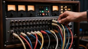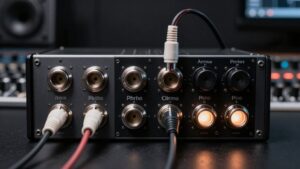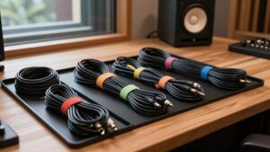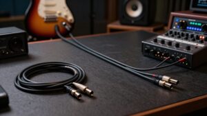
Audio Cable Types Chart: XLR, TRS, TS, RCA and MIDI at a Glance
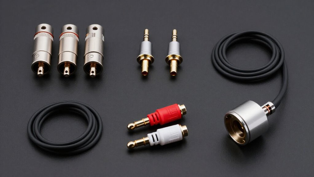
Use XLR (three pins) for balanced mono audio, especially microphones; use TRS (tip-ring-sleeve) for balanced mono or unbalanced stereo; and use TS (tip-sleeve) for short unbalanced instrument runs. RCA carries unbalanced consumer line-level audio, usually red/right and white/left.
Five-pin DIN MIDI sends control data, not sound, across up to 16 channels.
Keep TS/RCA near 4–5 m when possible, check phantom power before XLR connections, and never substitute instrument cable for speaker cable. More guidance follows.
Identify XLR, TRS, TS, RCA
Recognizing common audio connectors starts with their contact layout and signal format. XLR connectors typically use three pins and carry balanced mono audio, commonly linking microphones to mixers or audio interfaces. You can identify TRS and TS plugs by their insulating bands: TRS has two, whereas TS has one.
A TRS plug provides tip, ring, and sleeve contacts; depending on wiring, it carries balanced mono or unbalanced stereo. TS uses tip and sleeve for unbalanced mono signals, so you’ll often find it on guitars and effects pedals. RCA connectors carry unbalanced signals and usually appear as stereo pairs: white marks left and red marks right. You can also use RCA for digital audio. Check the connector’s intended equipment and signal path before making connections.
Connector Pinout Quick Chart
Use this quick chart to verify each connector’s contacts before you patch equipment: XLR uses pin 1 for ground/shield, pin 2 for hot, and pin 3 for cold in balanced mono wiring.
| Connector | Contacts | Typical use |
|---|---|---|
| XLR | 1 shield, 2 hot, 3 cold | Balanced mono |
| TS | Tip signal, sleeve shield | Unbalanced mono |
For TRS, you use tip, ring, and sleeve; its wiring supports either balanced mono or unbalanced stereo. On RCA, the center pin carries signal, while the outer shell provides ground/shield; follow white for left and red for right in stereo pairs. Inspect a 5-pin DIN’s 180-degree pin arc carefully, matching orientation before insertion. These contact assignments let you identify signal paths, shields, polarity, and channel roles without guessing for routine setup work.
MIDI Carries Data, Not Audio
MIDI transmits performance and control data rather than an audio signal, so it can tell a synthesizer which note to play, how hard to play it, when to change programs, or how to respond to controllers, aftertouch, and timing clock messages.
It can carry note numbers, velocities, program changes, control changes, aftertouch, and clock information across up to 16 channels, letting you address multiple instruments from one connection. With traditional five-pin DIN MIDI, your device’s OUT port sends data, IN receives it, and THRU forwards the incoming stream to another device. Because each cable normally carries data one way, you need separate paths for bidirectional communication. You can also use USB or compatible TRS minijack MIDI; Type A and Type B wiring must match.
Recommended Maximum Cable Lengths
You’ll minimize noise by keeping unbalanced TS and RCA runs to about 4–5 m (13–16 ft), or 25 ft at most, while balanced XLR and TRS lines support much longer distances. For digital systems, AES/EBU can maintain fidelity to 100 m (328 ft), whereas MIDI requires its own run-length limits because it carries data rather than audio. Choose a cable slightly longer than your route, but don’t leave excessive unused length that can collect interference.
Balanced Cable Distance Limits
Balanced XLR and TRS cables support long runs because their differential signal paths reject induced electromagnetic noise. You can use them for microphones, line-level feeds, and interconnects where equipment is separated by distances. The receiving input measures the voltage difference between the hot and cold conductors, canceling noise coupled equally onto both lines.
There isn’t a single maximum analog balanced-cable length: source level, output impedance, cable capacitance, electromagnetic environment, and input circuitry determine practical limits. For installations, use low-capacitance shielded cable and maintain wired connectors. If you’re carrying AES/EBU digital audio on balanced XLR, you can maintain fidelity for runs up to 100 meters (328 feet) under suitable conditions. Choose balanced connections whenever your routing requires distance, and verify performance in the installed environment.
Unbalanced Cable Distance Limits
Keep TS and RCA unbalanced audio runs to 25 feet (about 7.6 meters) or less, since their single-conductor signal path and shared shield make them susceptible to hum, RF noise, and electromagnetic interference.
For weak microphone or electric-guitar outputs, keep the cable shorter: aim below 13 to 16 feet (4 to 5 meters). These low-level, high-impedance signals lose noise margin, and longer cables behave as antennas that couple mains hum, lighting noise, radio-frequency energy, and electromagnetic fields into the program signal. When your equipment requires a longer connection, place a DI box near the source. It converts the unbalanced output to a balanced signal, allowing the extended cable segment to reject common-mode interference. Also route short unbalanced leads away from power transformers, AC cords, dimmers, and wireless transmitters.
Digital Signal Length Guidelines
Digital audio links follow interface-specific distance limits, so you should match both the cable type and its impedance to the signal format. For AES/EBU, use 110-ohm balanced XLR cable and keep the run at or below 100 meters (328 feet). This specification preserves the signal’s transmission characteristics and supports reliable balanced digital operation.
For Word Clock over BNC, use 75-ohm coaxial cable. The applicable maximum length depends on the clocking system; these guidelines don’t assign a universal limit. Likewise, optical S/PDIF and ADAT distances depend on the specific equipment and optical cable. Check each device’s documentation before extending an optical link, and avoid assuming that an analog cable’s distance guidance applies to digital interfaces. Use manufacturer-rated cables and verify stable lock during installation carefully.
MIDI Cable Run Limits
Unlike audio and clock links, standard 5-pin DIN MIDI supports cable runs of up to about 15 meters (50 feet). Treat it as a recommended maximum, not a routine target. Keep cables short; added length and capacitance degrade signal edges and data recognition.
If your installation requires a longer path, divide it with a MIDI repeater or an active distribution device rather than relying on one oversized cable run. Poorly made cables, unsuitable conductors, or high capacitance can produce missed notes, delayed commands, or corrupted messages before you reach the nominal limit. Verify the specific requirement for the connection type: this guidance covers 5-pin DIN MIDI links only. USB-MIDI uses separate USB signaling and must follow USB cable-length limits, power rules, and device requirements.
Minimizing Noise Over Distance
Cable length directly affects a connection’s susceptibility to electromagnetic interference, particularly with unbalanced wiring. Keep TS and RCA runs at about 25 feet (7.6 meters) or less to reduce induced hum and radio-frequency noise. For low-level microphone or electric-guitar signals, limit unbalanced cable to roughly 4 to 5 meters (13 to 16 feet); these sources are especially vulnerable to interference and capacitance effects.
Use balanced XLR or TRS for longer analog paths: differential inputs reject noise coupled equally onto both signal conductors. With suitable 110-ohm cable, balanced AES/EBU digital audio can maintain fidelity up to 100 meters (328 feet). Choose only the exact length you need, adding modest slack for equipment movement; don’t leave excess cable to collect interference or create unnecessary handling and routing complications during operation.
Balanced Cables for Long Runs
For long audio runs, balanced connections reduce interference by sending the same signal on positive and phase-inverted conductors alongside a ground. A balanced input rejects noise induced equally on both signal conductors by subtracting the inverted leg from the non-inverted leg.
Choose XLR or TRS cables only when both connected devices provide balanced outputs and inputs. For microphones, balanced XLR is the standard choice for extended stage or studio paths. Use balanced TRS or XLR for studio monitor feeds; TS and RCA are unbalanced and pick up more interference over distance. If a source has an unbalanced output, route it through a DI box to create a balanced line for longer runs. Balanced AES/EBU over XLR preserves audio fidelity to 100 meters (328 feet).
Check Phantom Power Before Connecting
Before you connect an XLR microphone or active DI box, verify whether it requires and supports phantom power. Phantom power supplies DC voltage, commonly 48 V, through a balanced XLR cable to operate condenser microphones and certain active DI boxes. Don’t enable it by default: many ribbon microphones and unbalanced devices can be damaged or operate incorrectly when phantom voltage is present.
Turn phantom power off before you plug in or unplug a microphone, then wait several seconds for the voltage to discharge. If your mixer or interface offers channel-specific switching, activate phantom power only on the input serving the compatible device. Use a standard balanced XLR path for phantom-powered equipment. Don’t assume TS or RCA connections can carry phantom power safely in practice.
Guitar Pedals to Amps
Once phantom-power requirements are clear, connect a guitar pedal’s output to an amplifier input with a ¼-inch TS instrument cable. A TS cable carries unbalanced mono audio, which matches the standard input/output arrangement used by most guitar pedals and amplifiers. Its plug has two conductive contact sections: the tip carries the signal, while the sleeve provides the return. One insulating band separates them.
Use a ¼-inch TS lead for this connection, plugging it into the pedal’s output jack and amp’s instrument input. Keep the run short; unbalanced cable becomes increasingly susceptible to interference and noise as length rises. When placement demands a longer distance, route the pedal signal through a DI box, which converts it from unbalanced to balanced audio for that extended run.
Diagnose Hum and Ground Loops
A ground loop occurs when interconnected audio devices have more than one ground path, allowing unwanted current to circulate and create a steady 50/60 Hz hum. You can isolate the source systematically without compromising electrical safety.
- Power every connected device from one properly grounded outlet or power strip, then listen for a change in hum level.
- Disconnect signal cables individually. If hum stops after you remove one link, inspect that device and its cable route.
- Use balanced XLR or TRS connections where available. They reject cable-borne interference, but won’t cure equipment-grounding loops.
- Never lift or defeat a mains safety ground. Install an appropriate audio isolation transformer, or have a qualified technician evaluate the system.
This approach identifies the offending path while preserving safe operation.
Speaker Cables Aren’t Instrument Cables
Speaker cables and instrument cables serve fundamentally different electrical roles, so you must not interchange them. Speaker leads carry amplifier-level power to passive cabinets; instrument leads carry weak pickup signals to amps or audio gear. Their construction reflects those loads:
- Use two suitably thick conductors for speaker runs, minimizing resistance and heat.
- Use shielded instrument cable: its center conductor carries signal, while its shield rejects interference.
- Never connect a shielded guitar lead between an amplifier and passive speaker; output current can overheat or destroy it.
- Choose speaker-rated connectors, preferably locking speakON. Although ¼-inch TS plugs may fit either jack, they don’t identify a cable’s rating.
For powered monitors, use balanced TRS or XLR cables from your interface or mixer, with one cable feeding each monitor.
Conclusion
With this chart, you can identify XLR, TRS, TS, RCA, and MIDI connections before you patch your system. You’ll choose balanced XLR or TRS for longer low-level runs, keep TS for instrument paths, and reserve speaker cable for powered outputs. You’ll also verify pinouts, cable-length limits, phantom-power status, and grounding when troubleshooting noise. By matching each connector and cable to its signal type, you protect equipment and maintain clean, reliable audio consistently.
Recording Storage & Session Length Calculator
Estimate uncompressed recording size per hour and per session, and how many hours fit on a card, from sample rate, bit depth and track count.