How to Use a Cable Tester to Find Faulty Studio Cables Fast
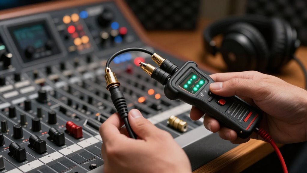
First, switch off +48 V phantom power and label both ends of every XLR cable. Set the tester to XLR mode, connect matching ends, and verify Pins 1, 2, and 3 map straight through.
Flex each connector and strain relief while testing to catch intermittent opens. Remove failed cables, inspect dark or crossed pins for damaged solder or contamination, then clean and retest. Tag fully passing cables green; the steps below sharpen your troubleshooting workflow.
Find XLR Faults in Minutes
To find XLR faults quickly, first confirm your cable tester’s battery has charge, then set it to the XLR position. Plug one cable end into the matching left-side XLR jack and the other into the right-side jack. Check that both connectors seat fully before reading results.
Advance the tester through each contact position. At every step, verify that the corresponding numbered pin indicates continuity from one end to the other. If a required pin shows no indication, suspect an open conductor, damaged solder joint, or loose connector contact. If the tester lights or indicates continuity between pins that shouldn’t connect, isolate the cable as a likely shorted lead.
Test your XLR inventory before sessions and again afterward. This confirms cables are ready for later use.
Disconnect Phantom-Powered XLR Lines
Before you disconnect an XLR line, switch off the mixer, preamp, or interface’s +48 V phantom power. This prevents live voltage from reaching your cable tester and protects equipment during troubleshooting.
Wait several seconds after disabling phantom power so the circuit can discharge, then unplug the XLR cable from the connected gear. Don’t attach a tester while the line remains powered; some testers can suffer damage from phantom voltage.
- Confirm the +48 V indicator is off.
- Pause briefly for stored voltage to discharge.
- Remove the cable only after power is off.
- Connect both cable ends to the tester’s matching XLR sockets.
Run the tester and inspect each pin result. A cable shows continuity on corresponding pins; any open, short, or crossed reading identifies the fault.
Step 1: Label Both Cable Ends
Label each studio cable at both ends with the same unique ID, such as MIC-01, before you begin testing. This lets you identify a disconnected cable. Place a durable, legible label near each connector, but don’t cover the plug, contacts, or strain relief. Use labels that withstand handling, and match every ID to your cable inventory.
Check that both ends carry identical text on cables with different connector types. A ID prevents you from assigning a tester result to the wrong lead when several cables are on the bench. Label cables before any measurements, then log pass, open, short, intermittent, or wiring results beside the corresponding ID. This records faults, speeds retesting, and clearly identifies the failed cable for future troubleshooting and inventory updates.
Step 2: Set Tester to XLR Mode
Confirm that the selector has clicked fully into position rather than sitting between modes. If your tester uses a menu, choose XLR and verify the mode shown on its screen before proceeding. Review the unit’s pin-indicator legend now: it should track pins 1, 2, and 3 individually. That reference helps you distinguish an open conductor, a short, or a swapped pin.
Step 3: Connect XLR Ends to Tester
With the tester set to XLR mode, plug each cable end into its matching labeled XLR socket—one at the main unit and the other at the remote or output jack. Align each connector’s keyway with the socket before insertion. Push it in straight until it seats fully and the latch engages, ensuring the pins contact the tester reliably. Don’t twist, force, or adapt a connector into a different jack; an incorrect fit can damage the socket or create a false fault indication.
Tug each plug lightly to confirm it’s locked and won’t shift during the test. Before you proceed, confirm the tester’s battery is working. A weak or depleted battery can produce inconsistent readings, so replace it if the power indicator is dim or absent.
Step 4: Verify Pin 1–3 Continuity
Once both XLR connectors are seated and the tester shows adequate battery power, set it to Pin 1 and check continuity between Pin 1 at each cable end. A beep confirms that the shield/ground conductor has an electrical path from one connector to the other. If you hear no beep, treat Pin 1 as open and remove the cable from service for repair or replacement.
Next, select Pin 2 and test Pin 2 to Pin 2, then repeat the process for Pin 3. Don’t compare different pin numbers; matching each contact at both ends lets you identify opens and incorrect wiring. Record any failed pin before retesting, and make sure the tester remains powered properly. A weak battery can produce unreliable indications, so recharge it.
Step 5: Wiggle-Test Intermittent XLR Connections
Intermittent faults often appear only when the cable moves, so connect the XLR cable to a tester with a remote end and run its continuity or pin-mapping test while you gently flex the cable near each connector. Wiggle the plug and cable at the strain relief, not the pins, and watch for flickering LEDs, a continuity beep that drops out, or a changed pin-map reading.
Repeat the procedure at several points along the cable. Check pins 1, 2, and 3 individually: a brief open or short on any conductor can disrupt balanced audio. If the failure occurs at a connector, re-terminate it or replace the connector. If it appears consistently at a point along the cable, replace the cable or have it repaired professionally.
Step 6: Remove Test Leads Safely
After completing the contact tests, turn off or disconnect the tester and any attached equipment before removing the cable. This prevents accidental stress on circuitry and protects gear from damage.
Grip each connector by its plug body, then pull it straight from the tester jack. Don’t pull on cable jacket, twist connector, or yank it sideways; those actions can loosen internal terminations, bend pins, or wear jack contacts. Once you’ve verified every contact position, remove both cable ends from their corresponding jacks.
Avoid touching pins or tester contacts unless necessary. Oils, debris, and oxidation can compromise future readings. Coil the cable loosely, keeping bends broad and preventing strain at either connector. Store it in a case where plugs won’t be crushed, contaminated, or snagged.
Tag Passing Cables Green
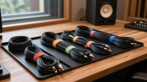
Mark a studio cable with a consistent green tag only when every contact passes the continuity test and each pin maps correctly from one end to the other. Run the check from both connectors before labeling the cable.
Confirm each terminal reaches its matching terminal, then attach the green tag directly to the jacket, where you can spot it during setup. Don’t tag a cable that fails, produces an uncertain reading, or hasn’t completed the full mapping check; isolate it for repair and retesting. After a session, teardown, or installation, test the cable again. Replace, add, or remove its tag according to the latest verified result. This routine prevents an old pass label from sending an unreliable cable back into your signal path safely.
Pin 2 Dark: Inspect Solder
If pin 2 stays dark on the tester, open the connector and inspect its solder joint for a cracked, cold, or incomplete connection. Verify that the conductor sits fully in the pin 2 cup and that solder bonds it securely. Check for stray strands bridging adjacent pins, lifted pads, damaged insulation, or movement when you gently flex the connector.
| Check | Fault sign | Action |
|---|---|---|
| Conductor | Loose or broken strands | Reseat and solder |
| Joint | Dull, cracked, or incomplete | Reflow with fresh solder |
Retest the cable immediately and confirm pin 2 lights consistently at both ends. If it remains dark after resoldering, trace the conductor along the cable for an internal break within its full length. Replace the cable if you can’t locate or reliably repair the fault.
Clean XLR Pins With Isopropyl
Unplug the XLR cable at both ends, then dampen a lint-free swab with 90% or higher isopropyl alcohol. Don’t pour alcohol directly onto either connector; liquid can migrate into the shell or cable and create a misleading test result.
Wipe each male pin and the surrounding contact area gently. Rotate the swab as you work so it lifts oxidation instead of spreading it. Use light pressure: XLR pins can bend, and scratching their plating reduces reliable contact. Avoid abrasive pads, wire brushes, or files, which wear through the conductive finish.
Inspect for residue, discoloration, or looseness after cleaning. Let both connectors dry completely before reconnecting the cable to your tester or studio gear. Then retest it; a restored pin reading points to contamination.
Conclusion
By isolating each XLR cable, disconnecting phantom power, and testing both ends systematically, you can locate opens, shorts, and miswired pins before they interrupt a session. Label cables, verify the tester’s pin readout, and inspect any dark or missing Pin 2 indication at the connector solder joint. Clean oxidized pins, retest after repairs, and tag confirmed cables green. This repeatable process keeps your studio inventory reliable and makes future troubleshooting faster, safer, and more precise.