Types of Audio Connectors: A Visual Guide for Home Studios
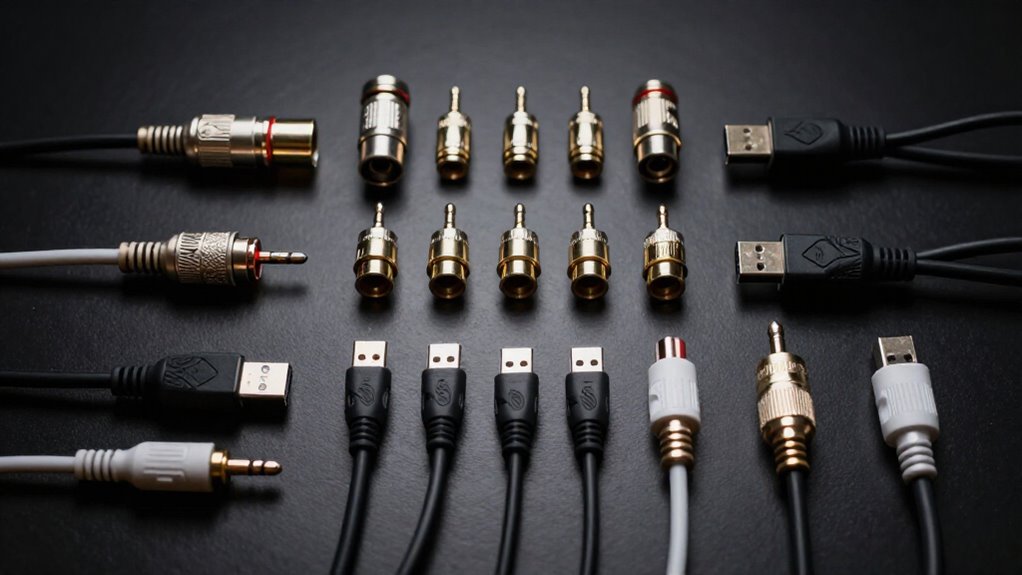
You’ll identify most home-studio connections by shape, pin count, gender, and signal role. Use three-pin XLR for balanced microphones, TS for unbalanced instruments, TRS for balanced mono or stereo, and RCA for consumer stereo pairs.
Match MIDI’s five pins and route Out to In. Use SpeakON only between an amplifier and passive speaker.
Check insert, mini-XLR, and TRRS wiring before adapting. You’ll also see how right-angle plugs, polarity, and clean contacts prevent common connection problems.
Connector Pin Counts and Genders
Before you connect studio gear, verify each connector’s pin count and gender. Pin count identifies the number of contacts, so it determines whether two connectors can mate. Microphone XLR connectors use three pins, but professional audio and lighting versions may use seven. Don’t assume that shells share the same wiring interface.
Gender identifies the mating side. A male plug carries pins; a female jack has holes. On a microphone cable, the female end connects to the microphone’s male output. Match both the connector’s gender and its pin count before you buy or patch a cable.
MIDI cables usually have five-pin connectors, and you must route each plug to the oppositely labeled In or Out port. Specialized microphones may use two- or three-pin connectors.
XLR, TRS, RCA Connector Comparison
Once you’ve matched pin count and gender, choose the connector type that fits the signal and equipment. XLR uses three pins and a locking shell, so you connect microphones to mixers with balanced lines. A ¼-inch TRS plug uses tip, ring, and sleeve; it carries balanced mono or unbalanced stereo, depending on wiring. Don’t confuse it with TS: one insulating ring identifies unbalanced mono instrument cable. RCA carries unbalanced audio; use its red/right and white-or-black/left pair for stereo. For runs, choose balanced XLR or TRS when gear supports it, since it reduces noise pickup.
| Connector | Signal capability | Practical use |
|---|---|---|
| XLR | Balanced | Microphone to interface |
| TRS | Balanced mono/stereo unbalanced | Line or headphone connections |
| TS | Unbalanced mono | Instrument cable |
| RCA | Unbalanced stereo pair | Consumer audio gear |
Right-Angle Plugs for Tight Racks
Right-angle TS, TRS, and XLR plugs turn the cable at the connector, saving space behind shallow racks and reducing strain on jacks near walls or panels. Match the connector to your device and signal, then choose an angle that routes the cable without blocking adjacent ports. Before buying, check the plug body, cable bend radius, orientation, and rack-door clearance.
Saving Space Behind Racks
When rack-mounted gear sits close to a wall or rear rack panel, right-angle plugs route the cable sideways or downward immediately after the jack, reducing required rear clearance and avoiding sharp bends.
They prevent cable jackets from pressing against the wall. Right-angle versions exist for ¼-inch TS/TRS and XLR connections, so you can match the connector format. Before installing them, check each jack’s surrounding clearance: neighboring sockets, mounting rails, and rear hardware can obstruct a bulky connector body. Confirm that the plug seats without contacting nearby hardware.
Don’t force a connector into a restricted space; pressure on the plug can strain the cable, loosen the jack, or damage its internal contacts. Use a fitted plug and leave room to connect and disconnect it safely.
Choosing the Right Angle
Choose a right-angle plug that turns the cable toward open space, not into an adjacent jack, rack rail, or wall. This orientation lets you place equipment closer together while keeping the cable exit clear of obstructions. Check the plug’s body width and its bend direction before you install it; even a compact angled connector can block nearby jacks.
Match the connector to the circuit’s requirements: use TS for unbalanced mono connections, TRS where stereo or balanced wiring is required, and the appropriate XLR version for XLR connections. Don’t force the cable immediately against the chassis. Leave sufficient clearance for a gentle run, so the bend doesn’t strain the plug’s termination or the cable’s conductors. Measure clearance with every neighboring plug installed first when possible.
Common Right-Angle Connector Types
In tight racks, 90-degree plugs route cables sideways instead of straight back, reducing the depth needed behind gear and near walls. Choose right-angle ¼-inch TS plugs for unbalanced mono instrument paths, including guitar-to-pedal and pedal-to-amp links.
Use right-angle ¼-inch TRS plugs when your equipment requires balanced mono audio or unbalanced stereo; the plug’s application depends on the jack and cable wiring. Right-angle XLR connectors suit balanced microphone lines and locking connections on mixers or rack-mounted equipment.
Before ordering, inspect panel’s jack spacing, cable exit direction, and surrounding hardware. A housing that points upward, downward, left, or right can occupy an adjacent jack or conflict with a rack rail. Match connector type to signal format, then confirm its body clears neighboring connectors in final position.
Reducing Cable Strain
Right-angle plugs reduce cable strain in tight racks by turning the cable alongside the equipment rather than forcing it sharply against a wall or adjacent unit. This routing reduces leverage on the connector jack, so a bumped or repositioned cable is less likely to transfer force directly to the socket. It also lets you place rack gear nearer to a rear wall without crushing the cable. Match the plug to the required connection and signal path: TS for unbalanced mono, TRS for balanced mono or stereo where applicable, and the correct XLR configuration for your equipment.
Even with an angled connector, don’t kink the cable at its exit point. Leave sufficient slack to form a gradual curve, which protects conductors, shielding, terminations, and jacks during use.
Clearance and Orientation
When rack-mounted gear sits close to a wall, a right-angle plug can route the cable alongside the chassis instead of straight out from the rear panel. This reduces rear-clearance requirements and helps keep connectors from contacting a rack door, neighboring equipment, or the wall.
Before choosing one, identify how its cable exits the plug body. A horizontal right-angle design may send the cable left or right, while a vertical version directs it up or down. Confirm that the selected direction suits the port layout and surrounding obstructions. Measure available space for both the connector housing and the cable’s bend radius; it’ll fit without pressure or a sharp kink. If you use an adapter, verify its connector types and audio wiring match the equipment’s ports.
Installation Tips for Tight Spaces
For tight racks, choose a right-angle plug that routes the cable into open space and reduces the depth required behind the chassis. First, measure the rear gap, then compare it with the plug body, connector housing, and the cable’s minimum bend radius. Don’t force the cable into a sharp turn; excessive bending can damage conductors and load the jack.
Check the plug’s orientation before ordering or installing it. Its exit path must face free space, not a rack rail, sidewall, or adjacent device. Verify that the connector and wiring suit the connection: use TS, TRS, or XLR as required by the device and cable. Finally, leave service slack so you can pull equipment forward and prevent cable weight from straining the plug or jack.
Locking SpeakON Connectors for Monitors
For passive monitors, you can use locking SpeakON connectors to secure high-current amplifier-to-speaker connections and prevent accidental unplugging. Match the connector’s pole count and wiring to your amplifier and monitor requirements, then use properly rated speaker cable. Don’t use SpeakON for active monitors, which typically accept line-level inputs through their built-in amplifiers.
Locking Mechanism and Safety
SpeakON connectors lock into place with a twist, preventing an amplifier-to-speaker cable from being pulled loose during operation. Retention protects your system from signal loss if a cable is tugged or a cabinet moves. Use SpeakON cables between a power amplifier and the passive speaker. These connectors are engineered for professional speaker-level connections where current is far higher than on typical line-level audio runs.
You shouldn’t use a SpeakON connection from your audio interface to active studio monitors. Active monitors contain their own amplifiers and accept line-level inputs instead. Compared with standard ¼-inch speaker plugs or XLR connectors, SpeakON’s locking design provides a more secure connection for high-current loudspeaker systems. Check that it is fully seated and locked before powering the amplifier for safe operation.
Connector Poles and Wiring
When wiring passive monitors, match the SpeakON connector’s pole count and terminal assignment to both the amplifier output and the speaker input. Check whether each device uses a two-pole or four-pole format, then wire only the terminals specified by its documentation. A common arrangement uses 1+ and 1− for one speaker circuit, but you must not assume that every amplifier and cabinet follows that layout.
Use dedicated speaker cable, not instrument or microphone cable, because the conductors must safely handle high current and voltage. Keep polarity consistent from output to monitor: connect positive to positive and negative to negative. Verify pinout labels before assembly, test each cable for continuity, and inspect the connector after locking it into place. Correct wiring preserves speaker operation safely.
Powered Versus Passive Monitors
Powered and passive monitors require different signal paths, so you must identify the monitor type before choosing a connector or cable. Powered monitors include their own amplifiers and normally accept line-level audio from an audio interface. Their inputs aren’t designed for an amplifier’s speaker-level output; connecting one can damage the monitor’s input stage.
Passive monitors, by contrast, require an external power amplifier. The connection between that amplifier and each passive speaker carries a high-current, speaker-level signal. In professional systems, locking SpeakON connectors provide a secure interface for these speaker connections. Their twist-lock design resists accidental unplugging, and their construction suits the current demands of larger PA and audio systems. SpeakON thus belongs on amplifier-to-passive-speaker links, not on line-level feeds to powered monitors in studios.
Cable Selection and Setup
For passive monitors, use locking SpeakON speaker cables between the power amplifier’s outputs and the speakers’ compatible inputs. Verify compatible SpeakON connections at each end, and confirm the cable’s current and power ratings meet your amplifier and monitor requirements. SpeakON carries high-current speaker-level signals, so select purpose-built speaker cable with the correct conductor gauge for the run length and load.
Insert each connector, then twist it until it locks; this prevents accidental disconnection while you position or operate your system. Don’t use an ordinary instrument cable in this path, because its construction isn’t intended for speaker power. Keep SpeakON connections between the power amplifier and passive monitors. Active monitors receive line-level audio from your interface, and you must never connect SpeakON to an interface.
Choosing Adapters for Insert Jacks
An insert jack combines a mixer channel’s send and return on one TRS connection, so you’ll typically need a TRS-to-dual-TS insert adapter. One TS plug carries the unprocessed signal to your external processor, while the other returns the processed signal to the mixer. Check your mixer’s manual or the jack labeling before connecting: manufacturers can assign send and return differently.
Match the adapter’s plug diameter to the equipment, usually ¼-inch (6.35 mm). Don’t substitute a standard stereo headphone breakout; it may look similar but won’t necessarily use insert wiring. If your compressor, equalizer, or effects unit has XLR, RCA, or other sockets, add required adapters on the send and return paths. Keep each path directed, then test the processor’s bypass and level controls before recording.
Cleaning Oxidized Connector Contacts
Oxidation on plugs and jack contacts can cause crackling, signal dropouts, or intermittent connections, so disconnect the cable or device from power before you clean it. Wipe accessible metal surfaces with a lint-free cloth lightly dampened with 90% or higher isopropyl alcohol, then allow them to dry completely before reconnecting. For recessed jack contacts, use a suitable small swab and gentle pressure; don’t force tools into the connector.
If oxidation persists, apply a contact cleaner labeled safe for the connector’s materials sparingly. Avoid household oils and abrasive tools, which can leave residue or damage plating. Inspect the contact afterward: if it remains pitted, badly corroded, or unreliable, replace the cable or have the connector professionally serviced. Don’t reconnect until all solvent has fully evaporated.
Mini-XLR’s Declining Studio Presence
Although Mini-XLR uses an XLR-style form factor, it isn’t a standard connector in most home-studio signal paths. You’ll encounter standard three-pin XLR far more often on microphones, interfaces, preamps, and other balanced audio connections. Its larger shell and locking latch provide a proven, secure connection that resists accidental unplugging during sessions.
Treat Mini-XLR as equipment-specific rather than as a default studio format. Before you buy a cable, inspect both device ends, confirm the connector’s pin arrangement, and verify whether the manufacturer specifies a dedicated wiring scheme. A physically similar connector doesn’t guarantee electrical compatibility. When you must connect Mini-XLR-equipped gear to a standard XLR input or output, use an appropriately wired adapter or cable. Don’t assume every adapter passes the required signals correctly safely.
TRRS for Smartphone Recording
For smartphone recording, a TRRS plug combines stereo headphone output and a microphone connection on four conductors—tip, two rings, and sleeve—separated by three insulating bands. Unlike a TRS plug, it carries headset playback plus a mic return, so you can monitor and capture audio through one phone port. Before tracking, connect your microphone to the headset jack or a compatible adapter, then verify that your phone detects the external input.
- Check the headset’s TRRS wiring standard; incompatible pinouts won’t pass microphone audio.
- Use a TRRS-to-TRS adapter when feeding a recorder or interface with a dedicated microphone input.
- Record a short test clip and monitor levels, routing, and noise before the session.
You’ll prevent silent takes and identify routing errors before committing to a session.
Conclusion
You’ll build a quieter, more reliable home studio when you match connector pin counts, genders, and signal formats before you buy cables. Use XLR for balanced microphone runs, TRS or RCA where your equipment requires them, and right-angle plugs in cramped racks. Lock SpeakON leads to compatible monitors, select insert adapters carefully, and clean oxidized contacts. Treat mini-XLR as legacy hardware, and use TRRS only when your smartphone’s input standard supports it directly, reliably, and safely.
Audio Interface Buffer Size & Latency Calculator
Convert audio interface buffer size and sample rate to milliseconds, estimate round-trip delay with your own overhead, and view a latency chart.
Headphone Drive Check: Will My Interface Power These?
Estimate whether an audio interface can drive your headphones: power in mW, maximum SPL and margin to your own target, with every step shown.
Recording Software Finder: Free & Paid DAWs and Recording Apps
Filter 23 verified recording apps and DAWs by price, license, platform, use case and feature, plus free DAWs bundled with interfaces.