How to Use a Patch Bay to Route Your Studio Without Re-Plugging
How to Use a Patch Bay to Route Your Studio Without Re-Plugging
You route your studio without re-plugging by placing device outputs on the patch bay’s top rear row and inputs on the bottom, then normaling frequent paths.
Use full normal to break defaults, half normal to tap signals, and thru for manual routes. Label points, looms, and normal states; document stereo pairs.
Patch from the front for alternate destinations, verify monitor left/right with a pan test, and inspect grounding if buzz appears. Next, refine connections.
Route Gear Without Replugging
Plan the patchbay around your signal flow so you can change routes from the front panel instead of reaching behind the rack. Place each device’s outputs on the top rear row and its inputs on the bottom rear row. Map your frequent source-to-destination paths first, accounting for rack position and cable length before installation.
Set those default paths to normalled connections, letting top-row outputs feed bottom-row inputs without patch cords. Choose full-normal when inserting a front-panel plug must interrupt the default route. Choose half-normal when you need a parallel feed while the original destination remains active. To reroute, patch a source output to another input at the front. For effects, patch a source into a processor, then route its output to an interface input. You’ll preserve stable defaults while creating alternate chains quickly.
Label Every Rear-Panel Connection
Label every rear-panel jack before you connect the looms, naming the device and signal role—for example, “interface output 3” or “compressor input.” Keep gear outputs on the top row and gear inputs on the bottom row, then add the patchbay and loom numbers to each label so you can trace any run across multiple units.
Use durable, machine-readable labels and place them where you can inspect them without disturbing cables. Mark the routing mode beside each pair:
- Full normal: inserting a plug breaks the default link.
- Half normal: a top-row patch taps the output while its default feed remains.
- Thru: no internal link exists; the patch cord defines the signal route.
Check each printed identifier against your installation plan before finally tightening the loom.
Step 1: Document Each Source-to-Destination Path
Document every normalled signal route before installation, tracing each source output to its destination input—for example, interface outputs 3–4 to SSL Fusion inputs, then Fusion outputs to interface inputs 3–4. Build a routing sheet that mirrors your physical layout. Give each path a unique line item, identifying the source device, output connector, destination device, and input connector.
Include patchbay number and loom number, particularly when signals cross multiple bays. Track stereo pairs as linked channels, but list individual point numbers so you can troubleshoot one side without guessing. Compare the sheet against rear-panel labels before you solder or terminate anything. Save a master copy, print a bench copy, and update both whenever you revise wiring. Clear documentation prevents misplaced returns, preserves signal flow, and makes a dense 96-point installation with hundreds of solder joints serviceable.
Step 2: Set Patchbay Normaling Modes
With your routing sheet established, set each patchbay pair’s normaling mode to match its intended default signal path. Choose full-normal when an output must feed its designated input until you intervene: inserting a plug in either front jack interrupts the rear connection. Choose half-normal when you need a default route plus an accessible split. A plug at the top-front jack taps the output while the normal continues; a plug at the bottom-front jack breaks it. Set independent connections to thru mode, which provides no internal top-to-bottom path and requires a front patch cable. Reserve normaled pairs for permanent workflows, including an interface output feeding a processor and its return feeding an interface input. Verify every pair’s setting on its switches or in its documentation.
Step 3: Patch Synth Outputs to Inputs
Route each synthesizer’s rear-panel output to a top-row patchbay jack, then wire the corresponding bottom-row jack to the intended mixer channel or audio-interface input.
Set the pair to full-normal when you want the default feed to disconnect when you insert a front-panel plug. Set it to half-normal when the input must remain fed while you tap the synth from the top-front jack for a destination. For a connection used only for manual patching, use thru mode. To redirect a synth, run a patch cable from its top-front output jack to the bottom-front jack for an alternate mixer or interface input. Label pairs by synth and destination, and keep output levels consistent. This layout preserves a default signal path while making rerouting immediate and visible.
Step 4: Patch Compressor Sends to Returns
A compressor follows the same patchbay logic, but it creates a send-and-return loop rather than a direct source-to-input path. Connect the compressor input to a top-row output carrying an interface or mixer send. Connect its output to the corresponding bottom-row input, which feeds the interface or mixer return. On a normalled bay, the send can reach its return by default; patch front-panel cables to insert the compressor into that signal path. For a channel insert, route the channel send to the compressor input, then route the compressor output to the matching channel return. Choose full-normal wiring when inserting a plug must interrupt the default connection. Choose half-normal wiring when you need a parallel split from the send while its normal destination remains connected intact.
Step 5: Calibrate Interface Output Levels
Before you patch the SSL Fusion, set your interface output level to a known, repeatable reference. Choose a fixed monitor or line-output setting and document it before you connect the interface to the patch bay. For this route, present interface outputs 3–4 on the bay, then patch them to the Fusion’s inputs. Return the Fusion’s outputs to interface inputs 3–4.
Use the same output reference whenever you compare the direct path with the Fusion-routed path. That consistency lets you judge processing rather than accidental level differences. Label the interface output points clearly and enter the chosen setting in your routing plan. When you rebuild the chain, you’ll restore the same gain structure and make reliable comparisons for future patch configurations without chasing level changes.
Step 6: Bundle Cables With Velcro
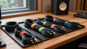
As you install the rear-panel connections, group related patch-bay cables into labeled looms and secure them with Velcro ties. Plan each loom’s length from the patch bay to its destination before terminating anything. This prevents strained runs that can compromise connectors and avoids excess cable that obscures signal paths. Keep low-level audio, line-level sends, returns, and control wiring in separate, purpose-specific bundles.
Don’t cinch Velcro tightly; leave enough movement to service connectors without stressing solder joints. Record every loom number, cable type, and the rear-panel points it serves in your wiring plan. When you add or reroute a circuit, loosen and reset the ties rather than dismantling the harness. In a dense build with roughly 500 solder joints, disciplined looms let you trace faults.
Confirm Left/Right Monitor Audio
With the rear-panel looms secured, label the patchbay’s left and right monitor outputs and their corresponding monitor inputs so channel identity remains unambiguous. Route your interface’s left output to the left monitor input and its right output to the right monitor input, preserving these default paths through the normalled connections. Play a pan test, then confirm that left program reaches left speaker and right program reaches right speaker. If either side is reversed, swap the relevant routing or rear connection and repeat the test. When needed, patch either monitor channel at the front panel and verify it interrupts the normalled path as intended. Clearly record each output, input, normal state, and alternate route in your patchbay plan for quick, error-free future session recall.
Diagnose Unbalanced-Cable Buzz
If an unbalanced-cable buzz appears in both your monitors and recordings, trace the connected signal path for a ground loop: multiple earth paths between studio devices can inject audible hum or buzz. Check each device’s mains grounding and every audio shield connection, one link at a time. In this patch-bay arrangement, the input carries hot and cold, but omits earth so you don’t add another earth route.
Cut back and insulate that unused earth wire; never leave it exposed. Don’t lift mains safety earth as a cure: retain it and use only properly designed, safe audio connections. Use the table to isolate the fault without changing safe power grounding.
| Test | Signal meaning |
|---|---|
| Buzz remains | Loop remains |
| Buzz stops | Last link implicated |
Document each result.
Clean Patch Points Quarterly
Once you’ve eliminated wiring-related buzz, keep patch points clean to preserve low-resistance, noise-free signal connections. Each quarter, power down equipment, inspect jacks and plugs, and remove dust or oxidation with approved audio contact cleaner. Apply sparingly: wet a plug, cycle the jack, then dry.
Maintain the wiring map while you work: identify every connection by gear, connector type, loom number, and patchbay number. Verify outputs remain on top row and inputs on bottom. Confirm full-normal pairs still carry their default routes and that the third-row splitter remains correctly labeled. Where input-side earth is intentionally omitted to limit ground-loop hum, check that the cut-back conductor stays insulated. The original 500-joint ADC 96+ installation took hours; quarterly cleaning protects that effort and keeps future rerouting fast.
Conclusion
With a labeled, documented patchbay, you control signal flow from one central point instead of disturbing rear-panel wiring. You set normaling to match your default routes, patch sources and processors deliberately, and keep cable bundles serviceable.
You verify stereo monitor polarity and level before sessions, then trace hum by isolating unbalanced runs and shared grounds. By cleaning contacts and updating your routing map quarterly, you preserve reliable connections, faster recalls, and repeatable studio operation throughout.