
How to Build a Studio Rack for Your Outboard Gear
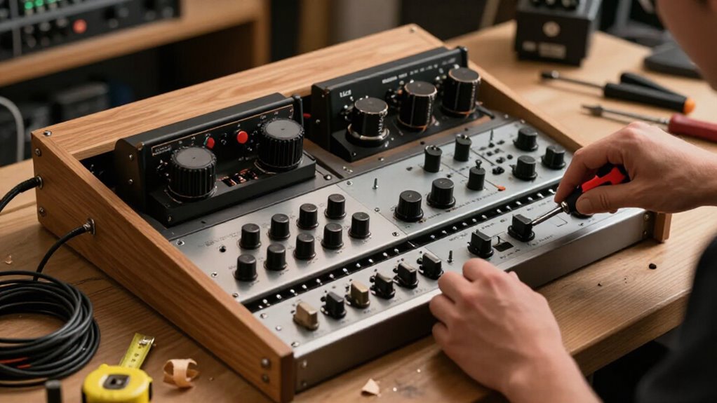
Build your rack around 14U, 19-inch rails, but verify their actual length before cutting.
Make the bottom 19 1/8 by 18 inches, use a 3-inch kick plate, and maintain clearance at the side opening.
Level the bench, dry-fit panels, square the cabinet diagonally, and install rear braces.
Set both rails 3/4 inch back, use compatible 10-32 screws every three or four holes, shim rocking rails, finish, add locking casters, and retorque annually.
Size Rack for 19-Inch Gear
Start by sizing the rack around standard 19-inch equipment and a pair of Middle Atlantic 14U rails. Use the rails as the reference for usable rack height, but verify their actual length before cutting because your enclosure dimensions may need adjustment.
Set the side-to-side opening to clear a 19 1/8-inch-wide kick plate, and make that kick plate 3 inches high. Cut the bottom panel to 19 1/8 inches wide by 18 inches long so it nests inside the kick plate and side panels.
Lay out each side panel from its bottom edge: measure up 3 inches, mark that point, then draw a diagonal from the mark to the end of the 16 3/4-inch top width. This slope establishes the front profile while preserving clearance for gear.
Gather Rack Rails and Screws
Gather the 19-inch rack rails and the rack screws that match their hole pattern before mounting anything. Rails have different hole patterns, so select screws that fit your chosen rail and planned mounting layout. Measure each rail’s setback; if it sits 3/4-inch behind the front edge, mark that position consistently. Check dimensions from both the top and bottom before fastening.
- Align the first rail to your marks and drive a screw every three to four holes.
- Repeat the same setback and vertical measurements on the opposite side so both rails remain parallel.
- Confirm the upper rail height before final tightening; gear near the top may sit beneath the lid and become harder to see during future servicing or patching.
Use compatible screws; don’t force threads into mismatched rail holes.
Step 1: Level the Assembly Surface
Before assembly, level the work surface so the rack base, sides, lid, and rails align without introducing a twist. Set a straightedge or spirit level across the full 19 1/8-inch bottom width and 18-inch length. Check front-to-back and side-to-side, then shim the bench or workpiece until both readings are true.
Dry-fit the bottom first, followed by the kick plates, sides, and lid. Press each piece against the surface and correct any rocking, gaps, or uneven edges before fastening. When you place the 14-space rails, verify they read level at their top and bottom, including the 3/4-inch back offset. Install screws every three or four holes, alternating positions as you tighten. This keeps the rails planar and prevents final tightening from pulling the assembly out of level.
Step 2: Mark Upright Panel Locations
Set the rack rails 3/4 inch back from your chosen front reference edge, then mark that setback once near the top and once near the bottom of each upright panel. Use the same front reference edge for every measurement; don’t measure from a shifting edge or an untrimmed corner. Connect the paired marks with a straightedge to create a clear alignment line for each rail.
Verify the distance between the left and right rail positions against your 14-space Middle Atlantic rails, adjusting the panel spacing as required for the finished 19-inch frame. Check both diagonals or measure across the layout to confirm the rails will remain parallel. Consider lid clearance before finalizing marks: equipment in highest spaces may be less visible under the lid.
Step 3: Glue and Clamp Rack Joints
With the panels dry-fitted and their alignment confirmed, glue and clamp the rack in a controlled sequence: install the bottom panel first, add the front and rear 3-inch kick plates, then attach the side panels. Apply a light, even glue film to each miter and mating edge; excess adhesive can shift parts or complicate cleanup. Seat the bottom tightly inside the kick plates and sides, then use elbow brackets to secure each connection cleanly.
These brackets prevent nail-gun gouges and keep future repainting or disassembly straightforward. Before tightening the side clamps, verify each kick plate follows its marked slant: begin 3 inches above the bottom reference and run the line to the 16.75-inch top width. Clamp across opposite corners and check diagonals for square.
Step 4: Install Rear Cross Braces
Once the bottom, kick plates, side panels, and lid are assembled, install the rear cross braces to lock the side panels together and stiffen the rack’s back end. Mark each brace location from your rail layout, maintaining the planned 3/4-inch rail setback and matching heights on both sides. Clamp the braces square across the rear, then pre-drill every fastening point to prevent splitting and keep alignment accurate. Drive screws at roughly every third or fourth available hole along each brace, creating a rigid connection that won’t loosen under equipment weight.
If you use elbow brackets, fasten them firmly at both ends; they simplify later disassembly or refinishing. Don’t rely on the lid: its one-inch overhang can limit top access and visibility, so the braces provide rear stiffness.
Step 5: Test-Fit a 1U Unit
Before you lock in the rail positions, cut a scrap 1U test piece and measure the clear interior width between the rails. Use this piece to confirm that the opening matches the 1U height and allows the test unit to slide squarely with clearance.
Set each rail 3/4 inch back from the front reference, then check that offset at both the top and bottom. Clamp or hold rails, then insert the test piece from front to back. It shouldn’t bind, rack, or contact the rear structure.
Check upper position: equipment installed near top must clear lid line. Fasten each rail with screws every third or fourth hole. After tightening, run the 1U test piece through more; fasteners can pull a rail out of alignment.
Step 6: Apply Polyurethane; Lock Casters; Vacuum
After confirming the rail alignment, complete the planned assembly, bottom, kick plates, sides, then lid, so you can finish every surface that will become inaccessible. Sand exposed wood to final grit, remove residue, and apply polyurethane in thin, even coats. Let each coat dry fully before recoating; this protects against scuffs and moisture. If you paint rather than stain, polyurethane still improves durability. For natural wood, finish after final sanding to preserve grain clarity.
Mount locking casters squarely beneath the base with hardware sized for the rack. They’ll let you roll it out for access, then lock securely during operation. Once coating has cured, vacuum the rack thoroughly. Remove dust from corners, joints, and base edges before debris collects beneath kick plates or lid.
Verify 10-32 Screws Thread Smoothly
Verify each 10-32 rack screw by hand-starting it in the rail or captive nut before using a driver. You should feel clean engagement within the first few turns. If a screw feels gritty, binds, or requires force, back it out immediately and realign it; angled entry can cross-thread the rail or nut. Don’t try to power through resistance.
Check that screw length suits the hardware stack, including the rail and any brackets. A screw that’s too long can bottom out, damage internal threads, and produce a misleadingly tight fit. When securing rails, use hole positions and install one screw every three or four holes. Tighten after each screw has started correctly. Then test a fresh 10-32 screw there. Smooth initial engagement confirms clean, intact threads.
Fix Rack Twist With Shims
Smooth screw engagement confirms the threads are sound; now correct any rack twist before permanently fastening the frame. Measure rail position at the top and bottom; their offsets must match. Shim the low side until both rails sit in one plane, keeping the specified 3/4-inch back offset.
| Check | Target |
|---|---|
| Top rail | Match offset |
| Bottom rail | Match top |
| Low corner | Add shim |
| Lid clearance | Check first |
Set elbow brackets loosely, insert shims, then align. You use screws every 3 or 4 holes to trap each shim. Verify alignment before mounting the lid’s 1-inch perimeter overhang; hidden joints are harder to correct. Recheck both rails with a straightedge across their faces. If one rail rocks, adjust shim thickness before tightening all bracket fasteners fully and securely.
Retorque Rail Screws Annually
Annually, retorque every rack-rail screw to keep outboard gear secure as vibration and temperature cycles gradually reduce clamping force. Before you tighten anything, verify that each rail still matches its original layout, including the approximately 3/4-inch setback. This check prevents a rail from creeping forward or backward while you restore tension.
Use the same well-chosen engagement points installed during assembly, inspecting every fastener along both rails rather than checking only the ends. A sound initial pattern uses one screw about every three or four holes, providing sufficient clamping force for yearly maintenance to be effective. Work methodically from one end to the other, tightening firmly without stripping threads or crushing the rail. Don’t skip upper screws because the lid’s roughly one-inch overhang obscures them.
Conclusion
You’ve now built a stable, serviceable rack that protects your 19-inch outboard gear and keeps connections accessible. Before loading equipment, confirm the rails sit square, every 10-32 screw threads cleanly, and casters lock securely. Shim any remaining twist rather than forcing components into alignment.
Let the finish cure fully, vacuum dust from the interior, and label cable paths. Recheck rail fasteners yearly, especially after moving the rack, to prevent looseness, vibration, and future gear damage.