Are Microphone Shock Mounts Universal? Fit, Diameter and Thread Checks
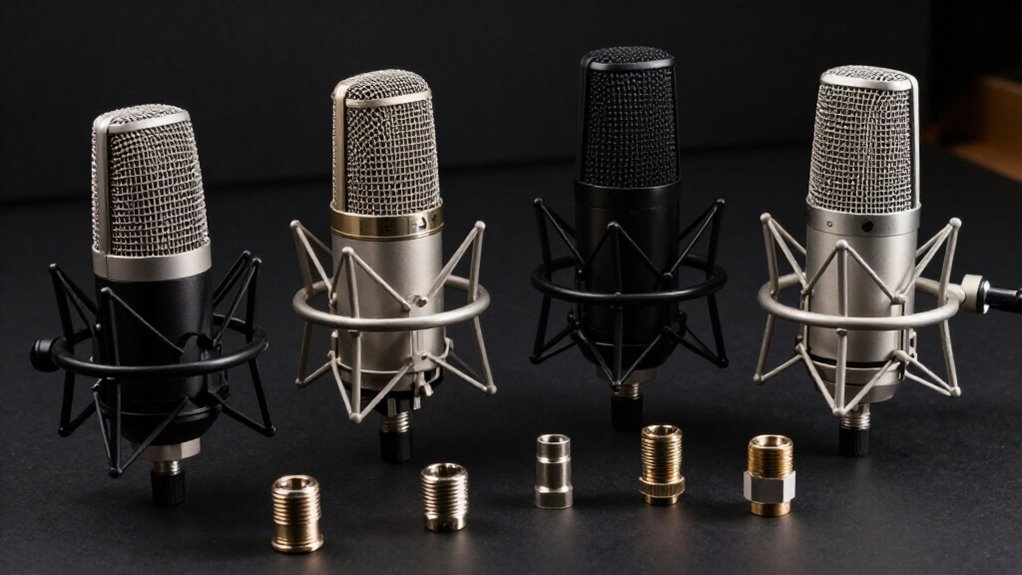
Microphone shock mounts aren’t universal: you must match your mic’s cylindrical body diameter, weight, and shape to the mount’s specified range. Verify the stand and mount thread diameter, pitch, and gender, typically 5/8-27, 3/8-16, or 1/4-20, and use the correct adapter.
Keep the mic centered, with taut elastics and clearance from the frame, XLR plug, and cable. Never force threads or an oversized body. Continue for checks on baskets, cradles, loads, and yoke spacing before you install.
Check 5/8-Inch Thread Adapters
Start by checking the thread standard on both the shock mount and the stand: most microphone hardware uses 5/8-27 threads, whereas camera tripods and many light stands use 1/4-20 screws. Verify not only the thread pitch and nominal size but also its gender: identify whether each connection is male or female. For a stand with a 1/4-20 female socket, a Wind-Tech M7 provides a 1/4-20 female-to-5/8-27 male conversion for compatible mounts.
Inspect microphone clamps for a removable 3/8-inch insert; it may already occupy the 5/8-inch connection. Don’t assume a 1/4-to-3/8 adapter completes a 1/4-to-5/8 interface. Before tightening, rotate the connector anticlockwise until it seats with an alignment click, then thread it clockwise gently. Stop if you feel resistance, since forcing it can damage the threads.
Match the Mic’s Diameter
After you confirm the thread interface, compare your microphone’s body diameter with the shock mount’s specified fit range. Measure the cylindrical section that the suspension cradle grips, rather than the grille, taper, switch housing, or connector end. Use calipers for the reliable result, and compare the measurement with the manufacturer’s minimum and maximum diameter figures. A microphone near the middle of that range usually provides the best clearance and support.
If the body is undersized, it can shift within the mount and lose positioning; if oversized, forcing it into place can distort the suspension geometry. Inspect the microphone from angles. It should sit centered, with even clearance around its circumference. Neither body nor controls should touch the outer ring, frame, or supporting structure.
Test Elastic Band Tension
Test the elastic bands by pressing the shock-mount basket upward firmly while the microphone is installed. A sound set moves about ¾ inch under this load while keeping the microphone centered. Confirm that the body never touches the outer ring at any point; contact bypasses isolation and transfers vibration directly to it.
| Check | Required result |
|---|---|
| Deflection | About ¾ inch |
| Centering | Mic stays centered |
| Clearance | No outer-ring contact |
| Fit | Bands stretch into clips |
Feel for springiness during installation: each band should resist insertion into its clips, not hang loose. Finished bands should match within millimeters.
Substantially slack elastic likely degraded. You can knot it temporarily, but replace it for isolation. Don’t overheat welded elastomer loops; excess melting can shorten them by an inch, producing excessive tension.
Compare Cradle and Basket Mounts
Cradle mounts suspend the microphone in elastic loops, so you must verify that the loops fit the body, center it, and prevent frame contact. Basket mounts support the microphone within an outer cage, requiring sufficient clearance from every structural ring to preserve isolation. In either design, inspect elastic tension and movement; degraded bands can let the microphone hit the mount and transmit vibration.
Cradle Mount Design
Unlike a basket mount, which surrounds the microphone in a larger suspension cage, a cradle mount holds it in an open frame with elastic bands or loops. You can load and inspect the microphone quickly, but verify that its body sits centered in the suspension. It must not touch the frame, because contact creates a direct path for handling vibration. Fit also depends on band geometry and clip capacity.
| Check | Specification | Result |
|---|---|---|
| Clip slot | 3 mm elastomer | Fits |
| Clip slot | 4 mm elastomer | Doesn’t fit |
Replace stretched or sagging loops before they allow the microphone to drift, contact the frame, or lose isolation. Measure band material; don’t assume similar-looking elastics seat correctly. A stable cradle maintains body clearance and lets you confirm alignment visually.
Basket Mount Support
Basket mounts use an outer frame and elastic loops to suspend the microphone, providing more enclosure than an open cradle mount while pursuing the same goal: interrupting vibration paths. Unlike a cradle’s open support points, the basket forms a rigid cage around the microphone and suspends it on elastic loops. You must keep the microphone centered, clear of all framework; contact transmits handling noise directly.
Inspect loops for stretch or sagging. Replace degraded loops instead of knotting them to remove slack. Match bands to the clips: tested clips accepted 3 mm elastomer belt material, not 4 mm. After fitting them, press the basket under light pressure in several directions. It should move freely and return the microphone to center without touching the outer ring.
Isolation And Compatibility
Whether you use a cradle or basket mount, isolation works only when the elastic suspension keeps the microphone completely clear of the rigid frame. In a cradle, inspect bands for stretch or sag. If the body touches the cradle, vibration bypasses suspension.
You can knot a loose band temporarily, but replace degraded elastic. A basket follows same principle, but its bands must fit clips precisely: 3 mm elastomer may fit where 4 mm won’t. After restringing, center the microphone and push the basket upward; it must remain clear of outer ring. A repair can allow ¾ inch upward travel under firm pressure without contact. Don’t judge compatibility by appearance. Measure microphone diameter and verify the attachment-thread size, since camera and stand threads can differ.
Account for Microphone Weight
Check the shock mount’s stated load rating against your microphone’s weight, since a diameter match doesn’t guarantee adequate support. Include the weight of any pop filter, capsule extension, or other accessory that the mount must carry. If the suspension sags or lets the mic contact the frame, you’ll lose isolation and transmit vibrations directly to the microphone.
Check Weight Capacity
Before installing a shock mount, compare its stated weight capacity with your microphone’s total supported load, including any attached cable, adapter, or windscreen. Verify it against the microphone body plus every supported item. An unsupported cable adds downward pull. Inspect elastic bands before testing; stretched, cracked, or softened bands can sag below their original performance.
| Check | What you observe | Required action |
|---|---|---|
| Centering | Microphone remains concentric | Confirm clearance |
| Ring clearance | Body touches no frame | Reposition or replace bands |
| Stability | Assembly sags or shifts | Replace degraded bands |
After mounting, gently orient the microphone as used and confirm it stays centered. Its body must never contact the outer ring or supporting framework. If it drifts, renew the suspension bands or select a mount that supports the complete installed assembly. This clearance test reveals suspension failure before vibration transfers into the microphone body during actual recording.
Match Mount Load Rating
A shock mount must support the microphone’s full installed weight within its specified load range. Compare the microphone’s published mass with the mount’s minimum and maximum rating; don’t assume that a physically compatible mount provides adequate suspension force. An under-rated mount can sag, shift the microphone off-center, or allow its body to contact the frame.
After installation, inspect clearance at the microphone’s normal operating angle and confirm that it remains centered without frame contact. If it hangs low despite correct installation, the suspension may be overloaded or its elastic loops may have lost elasticity. Heat, humidity, and aging stretch elastic elements, reducing support even when the mount originally matched the microphone’s weight. Recheck the mount’s load condition periodically and replace degraded elastic components promptly.
Consider Added Accessories
Mount load calculations should include the microphone plus every installed accessory, such as a foam windscreen, pop filter, cable clip, adapter, or compact wireless transmitter. Add them to the microphone’s mass, then compare the total with the mount’s load rating. Extra weight stretches elastic suspension, shifting resting position.
After installation, confirm the microphone stays centered and doesn’t sag into or contact the outer frame. Gently press and release the assembly to assess travel and clearance. In testing, replacement bands let the basket move upward about ¾ inch under firm pressure while preserving frame clearance. Finally, verify the stand and thread adapter support the load securely. Don’t assume thread compatibility equals load capacity: camera and microphone hardware may use standards, including ¼-inch and ⅜-inch threads.
Mounting a Blue Yeti
For a Blue Yeti, select a shock mount whose cradle matches the microphone’s body diameter and shape, since shock mounts aren’t universally sized. Confirm that the mount supports the Yeti while keeping its housing clear of the basket and outer frame; contact bypasses isolation and transfers vibration.
| Check | Requirement | Result |
|---|---|---|
| Fit | centered, taut elastic loops | no frame contact |
| Mount thread | 3/8-16 or 5/8-27 | stand-compatible |
| Tripod thread | 1/4-inch | camera-compatible |
| Adapter | matching male and female ends | secure interface |
Before tightening anything, inspect the suspension from every angle. The Yeti must remain centered when you gently move the assembly. Replace tired elastic bands rather than relying on tension adjustments; sagging loops let the microphone touch metal. Select an adapter only after you identify both thread genders and standards.
Leave Clearance for XLR Plugs
With the microphone seated and centered, connect its XLR cable before final tightening and verify that the plug clears the shock mount’s basket, frame, and elastic suspension. Route the cable exactly as you’ll use it, including any downward bend or strain-relief path. Inspect the connector body, latch, and cable boot from every angle while the mount hangs in its intended orientation.
You need a visible gap: neither the plug nor cable should press against rigid metal, plastic, or suspension bands. Contact creates a mechanical path that can carry handling vibration into the microphone and reduce the mount’s isolation. If clearance disappears after positioning, loosen the microphone clamp, adjust its depth or rotation, and retest with the cable attached. Don’t force; select a roomier mount.
Don’t Force 3/8-Inch Threads
Before attaching the shock mount, verify that its threaded socket matches the stand’s stud in both diameter and pitch. Many microphone stands use 3/8-16 threads, while larger models may use 5/8-27 or another standard. Similar threads can appear compatible but bind after only a turn or two.
- Inspect the published mount and stand specifications.
- Confirm whether a 5/8-inch clamp contains a removable 3/8-inch adapter.
- Fit the correct adapter before mounting.
- Rotate the connector anticlockwise until you feel a locating click.
- Then tighten gently; resistance at the first thread signals a mismatch.
Forcing a mismatched fitting strips the softer female socket or damages the stand’s stud. Stop immediately if engagement feels rough, uneven, or angled; recheck the size and pitch instead of applying more torque.
Measure Yoke Screw Spacing
Measure yoke screw spacing from the center of one mounting hole to the center of the other, not from their outside edges. Use calipers or a steel rule, keeping the tool square to the yoke. Record the center-to-center dimension in millimeters. Check screw diameter separately; matching spacing doesn’t guarantee screws fit.
Compare your measurements with the mount or stand specifications before ordering an adapter or replacement part, and also verify the listed hole size. If the spacing adjusts, set it where you’ll use it, then measure again.
Confirm that both screws align and start by hand without force. Don’t tighten screws that need sideways pressure or bind in the holes. Misaligned hardware can damage the threads or yoke.
Conclusion
Shock mounts aren’t universal, so you’ll get reliable isolation only when you verify the mechanical interface first. Check whether your stand uses 5/8-inch or 3/8-inch threads, then confirm adapter compatibility without forcing connections.
Measure your microphone’s body diameter, weight, yoke spacing, and XLR clearance. Choose a cradle or basket design that supports those dimensions, and confirm its elastic bands hold proper tension. For a Blue Yeti, use a mount designed for its size and mass.