
How to Organize Cables in a Home Studio: Labels, Trays and Noise-Free Runs
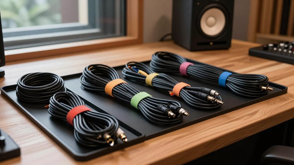
Start by photographing your setup, mapping routes, and labeling both cable ends with matching IDs and destinations. Power down gear, mount strips and adapter bricks in accessible under-desk trays, and use loose Velcro ties for serviceable runs.
Keep AC leads several inches from XLR, TRS, and instrument lines; cross them at 90 degrees. Leave service loops, inspect connectors, then listen for hum or crackle after startup. The steps below refine testing, maintenance, and fault isolation.
Moderate Two-Hour Noise-Free Cable Overhaul
A two-hour cable overhaul starts with a quick desk sketch: mark each device, group every lead as power, audio, or data, and measure its intended route with 10 to 15% extra length for bends and service loops. Then clear the work area and disconnect nonessential equipment.
Mount power strips and bulky adapters in under-desk trays, keeping their weight off signal paths. Run power along one desk side and audio along the other; maintain several inches of separation during parallel sections. Where routes must meet, cross them at 90 degrees.
Guide data cables through the remaining channel, avoiding pressure points, drawer slides, and hot adapters. Check each lead before reinstalling it: reject frayed connectors, crushed jackets, sharp kinks, or cables that cut out when flexed. Keep slack.
Gather Velcro Ties and Labels
Before you bundle or reroute anything, gather reusable Velcro ties and durable cable labels. These two supplies let you build adjustable, traceable runs without compressing insulation or creating hard-to-service paths. Choose ties in several lengths and labels that resist smearing, heat, and handling.
- Reusable Velcro ties for every cable bundle
- Short ties for 6 to 8-inch stationary bundle intervals
- Write-on or printable labels with strong adhesive
- Color-coded labels for cable categories or lengths
- Marked storage pegs for cable type or length
Fasten each stationary bundle roughly every 6 to 8 inches, but keep each tie loose enough to protect the jacket. Label both ends identically—for example, “MIC-01 to Interface In 1.” Include cable type and connection details, so you won’t confuse visually similar XLR and TRS lines during setup.
Step 1: Photograph Every Existing Connection
With Velcro ties and labels ready, document the studio’s current wiring before you unplug, bundle, or reroute a single cable. Photograph the system: desk, rack, patch points, floor runs, and any connections crossing into another room. Then take close-ups of both ends of every cable, framing the device name, port, label, and connector type. Clear images prevent confusion between similar XLR and TRS leads, where a mistaken reconnection can introduce hum, lost signal, or routing errors.
Photograph rack rears and other inaccessible equipment before you shift it. Record each cable’s path, bundle position, and exit direction, especially near power supplies or audio lines. Store the images beside your digital cable map. You’ll have a reliable restoration reference and a record for tracing faults later.
Step 2: Power Down Studio Gear
Power down the entire studio before you move, bundle, or disconnect any cable, since live connections can produce loud pops and expose equipment to electrical stress. Switch off monitors, amplifiers, interfaces, mixers, computers, and source devices in sequence. Doing so prevents transient signals from reaching speakers while you change the layout.
After every unit is off, unplug its power lead by gripping the plug body; don’t pull the cord or twist it in the socket. Confirm status lights are dark and external supplies are disconnected before handling signal, speaker, or data cables. Once reconfigured, inspect connections for secure seating, heat exposure, strain, and sharp bends. Correct problems before restoring AC power. Restore power gradually, with monitors and amplifiers last, then listen for abnormal noise.
Step 3: Separate Power From Audio Runs
Once the studio is powered down, route AC leads along one side of the desk or rack and keep microphone, guitar, and other low-level audio cables on the opposite side. Keep parallel runs several inches apart, because proximity can couple electromagnetic noise into sensitive signal lines. Bundle power cords separately; don’t zip-tie them to XLR, TRS, instrument, or other audio cables.
Where routes must intersect, make the crossing at 90 degrees rather than letting cables travel together. In a rack, assign separate paths or grommets to power and signal wiring, and keep XLR and AC bundles distinct. Balanced XLR and TRS connections reject interference more effectively on longer runs, but they don’t eliminate routing errors. Even cable can collect hum when you place it poorly.
Step 4: Install Under-Desk Cable Trays
Mount an under-desk cable tray or basket to lift power strips, bulky adapters, and excess slack off the floor while keeping the workspace serviceable. Choose a tray sized for your power strip, plugs, and adapter bricks, but leave every outlet reachable for testing, maintenance, and replacement. Feed cables into the tray along desk edges, and keep power leads apart from audio runs wherever the layout permits.
Leave a small service loop at each connection so you can unplug gear without strain. At moving joints, including standing-desk legs, form a hand-sized loop to preserve travel. Secure each bundle loosely with reusable Velcro ties, avoiding tight compression that can stress insulation.
Inspect tray clearance through the desk’s full height range, and confirm no cable rubs sharply.
Step 5: Add Ferrite Cores Selectively
With cables supported and routed, target ferrite cores only where you hear radio pickup, digital hash, or other RF interference. Ferrites aren’t replacements for proper shielding, grounded equipment, or sensible separation between audio and power runs. Identify the affected cable, then clip a sized core near the device where the interference enters. Follow installation guidance, ensuring the latch closes fully and the cable isn’t strained.
Monitor the system after each change at level. If noise remains, test a second core or loop the cable through a compatible core for impedance, provided its diameter and bend radius permit it. Compare before adding more hardware. Keep signal cables separated from power cables where practical; ferrites suppress RF, not hum from poor routing or grounding.
Step 6: Trim Tie Tails Flush
For permanent cable runs secured with zip ties, trim every excess tail flush against the locking head. Use sharp flush-cutters, positioning the flat side of the jaws against the tie head so you leave a smooth, low-profile edge. A clean cut prevents protrusions that can snag your hands, clothing, patch leads, or adjacent cable jackets during maintenance.
Work through each tray or bundle methodically, inspecting every tie after cutting. Don’t cinch ties tightly: they should hold the route in place without compressing insulation, deforming delicate audio cable, or restricting future service. Keep cutters away from cable jackets and cut one tail at a time for control. For runs you’ll revise, reroute, or replace, choose reusable Velcro ties instead. They secure the bundle without permanent tension.
Listen for 60 Hz Hum
After dressing and trimming each bundle, power up the studio and listen for a steady 60 Hz hum. A low-frequency tone often signals electromagnetic interference or a grounding issue. Note when it begins and whether its level changes when you touch connected equipment.
Trace runs first. Keep audio leads away from AC cables; when paths must meet, cross them at roughly 90 degrees. Use balanced XLR or TRS connections for longer signal paths, since they reject interference better than unbalanced instrument or RCA cables. If touching gear changes the hum, inspect the ground path. Power studio equipment from one strip or circuit to create a reference. Don’t replace cables blindly: a ground-loop hum won’t disappear with a new lead. Verify routing and grounding.
Crackling Channel: Clean TRS Jacks
Isolate a crackling TRS channel before assuming the cable run is at fault. Power down equipment, then confirm the plug and jack seat fully. Inspect both contacts for dirt, corrosion, looseness, or visible damage. Use a purpose-made contact cleaner sparingly and exactly as directed; let the jack dry completely before restoring power.
| Check | Method | Result |
|---|---|---|
| Seating | Reinsert fully | Rules out partial contact |
| Cable | Test known-good TRS lead | Separates lead from jack |
| Jack | Compare multiple leads | Identifies persistent fault |
Don’t force a plug or flood the socket with cleaner. If noise follows one cable, repair or replace it. If crackling remains with several known-good cables, stop testing and have the jack professionally inspected or repaired. This preserves reliable, low-noise signal paths throughout your studio setup.
Log Cable Replacements Quarterly
Reliable jack maintenance works best alongside a quarterly cable replacement log. Record the date, cable ID, type, and the gear or connection each lead serves. State why you replaced it: fraying, discoloration, crushed insulation, or an intermittent signal. These notes expose repeat failures before they become audible noise.
When a new cable changes an identifier or route, update your cable map and both-end labels immediately. At each quarterly review, inspect connectors and ties, and log every cable repaired, replaced, or marked suspect. Flag frequently replaced IDs, then examine their paths for sharp bends, heat exposure, and connector strain. You’ll isolate mechanical stress, correct routing faults, and preserve clean, dependable signal runs. This disciplined record supports faster troubleshooting and reduces avoidable hum, crackle, and downtime.
Conclusion
You’ve turned a tangled studio into a serviceable signal path. Keep power and audio separated, secure runs in trays with Velcro, and label both ends before you close the rack.
After change, verify continuity, monitor for 60 Hz hum, and clean TRS contacts. Photograph updates and log replacements quarterly. This routine reduces induced noise, speeds troubleshooting, protects connectors, and lets you reconfigure your studio without guessing and prevents avoidable faults during future swaps or repairs.
