Balanced vs Unbalanced Cables: How XLR and TRS Cancel Noise
You reduce hum on long runs when you connect a balanced source to a balanced input with fully wired XLR or TRS cable.
XLR uses pin 2 hot, pin 3 cold, and pin 1 shield; TRS uses tip, ring, and sleeve. The receiver reverses the cold leg and combines both legs, cancelling shared interference. An unbalanced TS connection doesn’t gain this protection.
Use a DI for distance. Next, you’ll find practical wiring and troubleshooting details.
XLR vs. TRS Pinouts
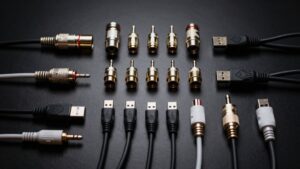
XLR and ¼-inch TRS cables can both carry balanced mono audio, but they assign the same three functions to different contacts. You must match each contact when wiring adapters or checking equipment: XLR pin 1 and the TRS sleeve provide ground/shield; pin 2 and tip carry hot (+); pin 3 and ring carry cold (−).
| Function | XLR | TRS |
|---|---|---|
| Ground/shield | Pin 1 | Sleeve |
| Hot / cold | Pins 2 / 3 | Tip / ring |
Hot and cold transmit opposite-polarity signal versions. Your balanced input compares them and rejects noise that both conductors collect equally. Don’t assume every TRS lead is balanced: it can also carry unbalanced stereo audio. Confirm the device’s connector specification before you connect it. This check prevents incompatible wiring and preserves reliable operation in use.
Phase-Inverted Signal Paths
Balanced audio uses two signal paths: hot carries the original waveform, while cold carries the same waveform with inverted polarity.
At the receiving input, a balanced-compatible circuit flips the cold path back to its original polarity. You can then combine both paths in phase, reinforcing the intended audio signal. This operation requires electronics designed for balanced reception; cable wiring alone can’t invert or restore a signal.
- Hot is the positive signal conductor.
- Cold carries an equal, polarity-reversed version.
- The receiver reverses cold before summing.
- XLR and TRS support this arrangement with two signal conductors and separate ground.
A TRS plug doesn’t automatically mean balanced operation: it can also carry left and right channels for unbalanced stereo. Confirm your source and destination correctly support balanced operation.
Common-Mode Noise Rejection
Because both signal conductors pick up external interference similarly, a balanced receiver can reject this common-mode noise while preserving the intended audio. Your XLR or TRS link sends matching audio on two signal wires, but one carries opposite polarity. Along the cable, electromagnetic fields may induce identical voltage on both conductors.
At the input, the receiver reverses the inverted audio path and combines it with the non-inverted path. Desired signals reinforce each other, while shared interference cancels. This benefit requires a balanced source, cable, and compatible balanced input; connector shape alone doesn’t create common-mode rejection. The separate conductor provides shielding and a ground reference, but it doesn’t perform cancellation. You get best rejection when both signal conductors receive closely matched interference over the cable’s full length.
Field Termination and Troubleshooting
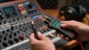
Correct field termination preserves the signal polarity and shielding that a balanced link requires. On XLR, wire pin 1 to shield/ground, pin 2 to hot (+), and pin 3 to cold (−); verify each device’s pinout first. For TRS, use tip hot, ring cold, and sleeve shield; its two insulating rings identify the contacts.
- Test continuity from every conductor to its intended terminal.
- Check that hot, cold, and ground have no shorts.
- If hum appears, inspect plugs and solder joints, confirm balanced support at both devices, and separate audio from power cables.
- When adapting to an unbalanced input, follow its documentation for the cold conductor; you’ll lose balanced noise rejection.
A reversed polarity connection can reduce signal integrity and complicate diagnosis during live service.
Phantom Power Device Compatibility
Phantom power sends typically +48 V DC through an XLR cable, placing the same voltage on pins 2 and 3 relative to pin 1. Before you enable it, confirm that your microphone is designed to accept phantom power. Consult the manual, particularly when you use a vintage microphone or ribbon model.
A wired balanced dynamic microphone usually tolerates phantom power because both signal conductors receive equal DC potential. However, a damaged cable, miswired connector, or adapter can create a voltage difference that risks damage.
Don’t treat TRS as phantom-power compatible by default; its suitability depends on wiring and on whether the connected device is built to supply or receive power. Likewise, verify XLR-to-TRS or XLR-to-RCA adapter pinouts and device specifications before connecting.
XLR Latch Replacement Costs
After confirming safe cable wiring and device compatibility, inspect the XLR connector’s latch if it no longer locks securely. Replacement costs aren’t fixed: they depend on cable model, latch geometry, and the repair provider. The latch itself may cost little, but bench labor and shipping can exceed its hardware price. Before authorizing work, compare the quote against a compatible replacement connector or complete cable.
- Identify the connector’s manufacturer and exact series.
- Verify that the latch matches its housing and release mechanism.
- Confirm installation won’t damage solder joints or internal wiring.
- Review warranty repair or replacement terms before opening the connector.
If you choose a technician, request an itemized estimate covering parts, labor, and return shipping. Latches aren’t always economical if connector wear requires service.
Ground-Loop Hum on Long Runs
Why can a long audio run hum even when you use XLR or TRS cables? A ground loop can form when connected devices sit at different ground potentials. That difference drives unwanted current through the cable shield, producing hum.
Balanced lines reject interference that reaches hot and cold conductors equally, but they don’t automatically stop shield-current hum. For runs beyond about 25 feet (7.6 meters), use balanced XLR or TRS connections: the source must provide a balanced output, destination needs balanced input, and all three conductors must remain connected. A balanced cable alone won’t convert unbalanced gear into a noise-rejecting link.
If hum persists, check device grounding and connection requirements. Don’t lift or disconnect the shield; that can create a safety hazard.
Cable Capacitance and High-Frequency Loss
As you increase cable length, you add capacitance that can interact with the source’s output impedance and roll off high frequencies. You’ll notice this most with high-impedance sources, such as passive guitar pickups, rather than low-impedance mic or line outputs. Balanced wiring doesn’t prevent this loss, so check capacitance ratings and keep high-impedance runs short.
Cable Length and Capacitance
Cable length directly affects capacitance: every foot or meter adds to the cable’s total capacitance, which can form a low-pass filter with the source impedance and reduce high-frequency content. Because capacitance is rated per unit length, you should multiply that specification by your planned run and compare cable data before buying. High-impedance sources, especially passive guitar pickups, are more sensitive than low-impedance outputs.
- Keep unbalanced connections under 15 to 20 feet (4 to 6 meters) whenever practical.
- For longer balanced runs, check both source impedance and capacitance.
- Balanced wiring rejects interference, but it doesn’t remove capacitance effects.
- Runs of 50 to 100 feet (15 to 30 meters) are common, provided equipment specifications support them.
Measure the actual route; spare cable adds capacitance too. Choose low-capacitance cable for demanding sources when possible.
High-Frequency Roll-Off
High-frequency roll-off occurs when a cable’s capacitance interacts with the source’s output impedance to form a low-pass filter. As cable length rises, capacitance rises and the filter’s cutoff frequency can fall, reducing treble. You’ll notice this most with high-impedance sources, particularly passive guitar pickups driving long instrument cables.
Balanced wiring doesn’t inherently stop this loss: cable capacitance, run length, and source impedance set the result. Use a shorter, lower-capacitance cable when preserving pickup brightness matters. For typical line-level gear, output impedance is usually low enough that ordinary cable lengths produce little audible high-frequency roll-off. If you need a long instrument run, place an active buffer or DI near the instrument; its low-impedance output drives the cable more effectively and maintains a higher cutoff frequency.
Guitar Pedals and DI Boxes
Your pedals typically use unbalanced ¼-inch TS connections, so a balanced cable won’t make the pedal-to-amp signal balanced or eliminate noise. Keep these runs short, about 15 to 20 feet (4 to 6 m), especially around power supplies and transformers. When you need to reach a mixer or interface, place a DI box near your instrument or pedalboard and run balanced XLR from the DI to the balanced input.
Pedal Outputs and Noise
Most guitar pedals use unbalanced TS inputs and outputs, so plugging one into a balanced cable won’t make its signal balanced or cancel induced noise. Keep your pedal-to-amp TS runs under 15 to 20 feet (4 to 6 meters) whenever possible to limit hum and electromagnetic interference.
- Treat the pedal output as unbalanced, regardless of cable connector style; its wiring doesn’t create a differential signal for rejection.
- Short TS cables reduce the antenna length that can collect mains hum, lighting noise, and radio-frequency interference around you onstage.
- Near your pedalboard, a DI box converts its output to balanced XLR before a cable crosses the room to mixer.
- Verify the DI output and input requirements; an unbalanced destination discards balanced noise reduction entirely at receiving end of the system.
When to Use DI
A DI box becomes useful when an unbalanced guitar or pedalboard signal must travel more than about 15 to 20 feet (4 to 6 meters), particularly across a noisy stage or through a stage snake. Connect your guitar or pedalboard output to the DI instrument input, then send its XLR output to the console or stage snake. The DI converts the unbalanced source into a balanced signal, reducing interference picked up along cable path.
If you hear low-frequency hum from a ground loop, engage the ground-lift switch according to the DI manufacturer’s instructions; don’t use it for routine tone control. You usually don’t need a DI for a short guitar-to-amp cable, where the unbalanced run remains brief. Skip it if your gear provides a suitable balanced line-level output.
Balanced Runs to Mixers
Because guitar pedals usually use unbalanced TS connections, a balanced cable plugged into a pedal won’t create a balanced signal.
For a long run to a mixer, place a DI box after your pedalboard. It converts the unbalanced instrument signal to a balanced output, usually on XLR. Connect that XLR to a balanced mixer input so common-mode interference is rejected across the cable run.
- Put the DI after the final pedal.
- Use the DI’s XLR output for the long cable.
- Engage ground lift if a ground loop causes hum.
- Skip the DI only when your device provides a true balanced line-level output and the mixer accepts it directly.
Match output level and input type, and keep short unbalanced links between pedals and DI box.
Prefer XLR for Stage Microphones
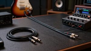
For stage microphones, use balanced XLR cables to minimize hum, buzz, and radio-frequency interference over long runs. An XLR microphone lead carries the audio on hot and cold conductors, which receive much of the same induced noise along the route. At the balanced input, the receiver subtracts the two signal legs, preserving the desired audio while canceling noise common to both.
A separate ground conductor and shield protect the pair from external fields and provide a reference path. This design makes XLR practical for microphones, stage boxes, and mixers, especially in busy venues. Still, don’t route mic cables near AC mains, power supplies, or dimmers. Confirm both microphone and receiving input support balanced XLR connections; otherwise, you won’t get the full common-mode noise-rejection benefits.
Conclusion
Choose balanced XLR or TRS connections when you need low-noise audio over long runs. You send equal, opposite-polarity signals, so a differential input rejects noise induced equally on both conductors. Check pinouts, shield continuity, and device compatibility before troubleshooting hum. Use DI boxes to balance instrument-level pedal outputs, and avoid phantom power on unsupported equipment. For stage microphones, prefer XLR: it locks securely, carries phantom power, and maintains reliable common-mode noise rejection in practice today.