Normalled vs Half-Normalled Patch Bay: Which Mode for Which Gear?
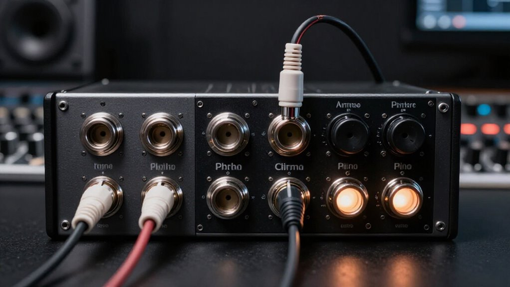
Use full-normalled pairs for default routes, such as a console output to an interface input, when a plug at either front jack must break that connection.
Use half-normalled pairs when you need a source tap: patch the top jack to feed a compressor, recorder, or meter while its normal destination stays fed; patch the bottom jack to replace the destination.
Keep effects returns non-normalled. Label modes. Further guidance helps you prevent accidental mults and feedback.
Default Routing Without Patch Cables
Without any front-panel patch cables, a normalled patch bay routes each upper rear jack, usually an equipment output, to its corresponding lower rear jack, usually an input. This internal top-to-bottom path carries your source to its assigned destination, so you don’t need separate rear patch cables for routine connections. You can leave commonly paired gear, such as a preamp output and converter input, connected by the bay’s default route. Both full-normal and half-normal configurations establish this unpatched path; their operational distinction appears only after you use the front panel.
| Rear position | Default role |
|---|---|
| Upper jack | Equipment output |
| Lower jack | Equipment input |
| No plug | Top-to-bottom connection |
| Through bay | No default route |
You must use a patch cable to connect them; label pairs and always verify output-to-input orientation carefully.
Rear-Jack Signal Path Differences
The default top-to-bottom route changes according to which front jack you patch. In both full-normalled and half-normalled modes, the upper rear jack normally feeds directly to its paired lower rear jack until you interrupt the complete normalling path. With full normalling, inserting a plug into the top front jack opens that rear connection: the source appears at the top front jack, but it no longer reaches the lower rear jack. With half normalling, a top-front insertion doesn’t open the rear path; the source continues to the lower rear jack.
In either mode, inserting into the bottom front jack breaks the normal route, so you can redirect the destination input. In thru mode, no rear-to-rear link exists; each rear jack connects only to its matching front jack.
Parallel Recording Output Access
With a half-normalled pair, you can record a parallel copy of a source without disrupting its normal destination: connect the source to the top rear jack, the destination to the bottom rear jack, and the recorder input to the top front jack. That front connection preserves the rear normal, so both inputs receive the same line-level signal. Check operating levels and input impedance before committing the split to a session in advance.
- Use this path to capture a safety track, alternate recorder, or measurement feed.
- Confirm the source output can drive both connected line-level inputs without loading or level loss.
- Keep power-amplifier outputs off this split; they aren’t suitable patch-bay sources.
- Choose full-normalled mode when a top-front plug must interrupt the default destination route.
Front-Panel Repatching Complexity
Front-panel repatching changes in complexity according to the bay’s normaling mode: a full-normalled pair breaks its default route when you plug into either front jack, so you must patch the source to its new destination explicitly. This makes every intervention unambiguous: inserting a plug removes the normal and establishes the path you choose.
With half-normalled pairs, plugging into the top jack preserves the normal, so you can tap the source for monitoring or an additional feed while the original destination stays fed. To substitute the destination’s input, patch the bottom jack; it breaks the normal and accepts another source. Choose full-normalled when you want front-panel changes to interrupt routing; choose half-normalled when you need fast branches. Non-normalled pairs require patch cables for every route.
TRS Insert Loop Requirements
Before you patch a console insert loop, confirm that the insert uses TRS wiring that carries the channel’s send and return on a single cable and that your bay’s jack assignments match that pinout. That check prevents reversed contacts and gives you predictable signal flow through external processing. Check your TRS cables too; they must carry both paths correctly.
- Wire the bay’s top jack as send and its bottom jack as return, following your console documentation.
- Use half-normal mode so the default insert loop remains connected without front-panel patching.
- Patch the top jack to tap the send while the normal route stays intact.
- Patch the bottom jack to break the normal and reroute the return through line-level equipment only; never connect power-amplifier outputs.
Contact Cleaning and Replacement Costs
Normalled paths depend on leaf-spring contacts that open when you insert a plug and reconnect when you remove it, so oxidation or weak spring tension can interrupt the default signal route. Clean the bay with a contact cleaner approved for its jack materials, then test each normalled route by monitoring continuity and passing program signal.
The leaf springs sit inside the jack assembly, so they’re less accessible than patch-cable jack contacts and may resist routine cleaning. On lower-cost bays, treat unreliable spring contacts as a probable early failure point. If cleaning doesn’t restore stable continuity, arrange repair or replace the affected bay; manufacturers and service providers set the actual cost, so inspect your warranty, labor options, and replacement availability before committing to either option.
Accidental Multing and Feedback Hazards
Half-normalled bays can create an accidental mult: patching from the top jack sends the source to the new destination while its normal connection remains active. That split is useful for feeding a recorder and processor, but verify both destinations before you patch. An unnoticed duplicate can drive equipment you didn’t intend to feed.
- Use the top jack only when you want a parallel feed.
- Patch the bottom jack to break the normal and replace its destination.
- Choose full-normalled pairs when either front-panel patch must interrupt the default route.
- Before connecting an effect send or return, trace the loop: a default loop-back can form feedback and damage the unit.
Mute monitors, lower sends, and confirm return paths before restoring level. Prevent runaway recirculation during testing.
Labeling Errors and Recall Speed
Label each pair with its source, destination, and normaling state so you can predict the signal path before patching. For half-normalled pairs, note that the top jack preserves the normal route while the bottom jack breaks it. Keep a matching wiring diagram so you can recall default routes quickly and identify intentional changes.
Label Normaling States Clearly
Clear labeling turns a patch bay’s default signal flow into an immediately readable map. You should identify both the device and its role at every pair: “Drum Machine Out” above “Mackie In,” for example. Then mark the pair’s normaling state directly on the front panel.
- Full-normalled: either insertion interrupts the default connection.
- Half-normalled: a top-jack patch taps or splits the source while its lower route remains; a bottom-jack patch breaks it.
- Non-normalled: no internal route exists; you must patch every connection.
- Match each label to your intended default workflow, since bay configurations vary.
These visible distinctions separate normal routes from temporary cable changes. You’ll avoid sending audio to the wrong destination and can verify signal flow at a glance during setup or troubleshooting sessions.
Speed Recall With Documentation
Accurate documentation turns those front-panel normaling labels into fast, repeatable recall. Label every patch point with its assigned device and input or output, so you can verify the default signal path at a glance. Keep these names on the bay’s scribble strip; labels hidden in a session file won’t help while you’re repatching.
Before installation, draw a wiring diagram that identifies each link as full-normal, half-normal, or non-normal. Include cable labels in your recall notes. A patched cable marks a possible departure from the documented default, even when jack labels remain correct. Record your operating method, too: on a half-normal pair, patching the top jack taps the source while preserving the normal; patching the bottom jack interrupts it. This prevents errors, restoring routing quickly.
Compressors, Interfaces, and Effects
You can fully normal your console-to-interface path through a compressor so its input and output stay in the default route until either front jack breaks the connection. Half-normal a source output to an interface input when you need to record it while tapping the top jack for another destination. For effects, use half-normalled sends for parallel processing and non-normalled points for connections that should exist only when patched.
Interface Output Normaling
A full-normalled interface-output pair routes the interface’s top rear output directly to the compressor’s lower rear input until you intervene. Routine assignments stay stable.
- Use full-normaling when the compressor should receive that interface output by default.
- Patch the top front jack to break the normal, then make any required downstream connection at its designated points.
- Use half-normaling when you need the interface output to keep feeding the compressor while also sending a copy elsewhere.
- Patch the bottom front jack of a half-normalled pair to break the normal and deliberately reroute the destination.
Keep effects returns and occasional processors on non-normalled points, so they exist only when you patch them. This layout preserves predictable signal flow while giving you access to parallel feeds and overrides.
Compressor Insert Routing
Compressor insert routing applies those normaling choices to a complete processing path between the console, compressor, interface, and any optional effects. With a full-normalled pair, put console output on the top rear jack and interface input on lower rear jack. The default connection feeds the interface without external patching under normal operating conditions. Patching the top front jack to compressor input breaks it; patch compressor output to lower front jack to restore the route through compression.
With half-normalled wiring, patching the top front jack feeds compressor while console still feeds interface. You can record dry and processed line-level signals if neither input overloads source. To make compression the sole destination, patch lower front jack, breaking normal, then complete compressor return. Never split power-amplifier outputs.
Effects Send Flexibility
Effects-send flexibility depends on whether the patch bay must preserve a default route, create a parallel feed, or remain disconnected until you patch it. Choose routing for your console outputs, interface inputs, compressor, and effects.
- Use a full-normalled pair for a console-output-to-interface-input default. Inserting into either jack breaks the route, so you can place a compressor inline.
- Patch the top jack of a half-normalled pair to feed an effect while the original signal still reaches its destination.
- Patch its bottom jack when you need to break the normal and substitute an effects return or another input.
- Use half-normalled splitting to record dry audio at the interface while feeding line level to processing; choose non-normalled pairs when effects should connect only through a patch cable.
Choose Switchable-Normaling Patchbays
Choose a switchable-normaling patchbay when your studio needs mixed signal-flow behavior across different jack pairs. You’ll gain per-pair control: use full-normalled connections for default routes that must break when you insert a cable into either front jack. Set half-normalled pairs where patching the top jack should split the source while the lower jack continues feeding its normal destination. Configure non-normalled pairs when you want no internal route and prefer every connection to use a patch cable.
Before you buy, count the inputs and outputs you’ll need, including effects sends, returns, console channels, and outboard I/O. Verify that each pair supports full, half, and non-normalled operation. Then draw a wiring plan that labels every pair’s default source, destination, and interruption behavior. This prevents configuration mistakes.
Conclusion
Use full-normaling when you want a default source-to-destination path that breaks completely as soon as you patch either front jack. Choose half-normaling when you need a parallel tap, such as sending a preamp to both your interface and a recorder, without interrupting the primary route.
Reserve isolated pairs for insert loops and effects. Label every pair clearly, verify TRS wiring, and prefer switchable-normal bays so you can adapt routing without rebuilding your entire studio.