Acoustic Panel NRC Rating Chart: Absorption by Material and Thickness
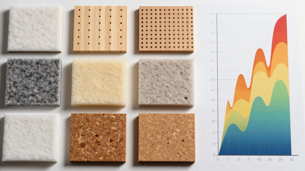
Acoustic Panel NRC Rating Chart: Absorption by Material and Thickness
You can’t compare acoustic panels by thickness alone: ASTM C423 results depend on material, density, facing, backing, and mounting. As guidance, a 0.5-inch porous panel may reach NRC 0.50, a 1.5-inch foam or fiberglass panel about 0.75, and high-performance products near 0.95.
NRC averages 250 to 2,000 Hz, so check 125-Hz coefficients for bass control. Use sabins and RT60 to size coverage; mounting gaps and finishes can change results. The details below show how to specify accurately.
ASTM C423 Test Conditions
ASTM C423 measures an acoustic panel’s sound absorption in a reverberation chamber by comparing the room’s reverberation time before and after technicians install the test specimen. During the procedure, you expose the specimen to broadband sound and measure absorption coefficients at standard octave-band frequencies, including 250, 500, 1,000, and 2,000 Hz. You calculate Noise Reduction Coefficient (NRC) by averaging those four coefficients, then round the result to the nearest 0.05.
This single number characterizes mid-frequency absorption rather than total acoustic behavior. It excludes the 125 Hz band, so you should review the complete frequency-specific data when low-frequency control matters. Treat each reported value as specific to the tested specimen and its mounting configuration; backing, air space, and installation conditions can directly alter measured absorption.
NRC by Thickness and Material
Thickness influences an acoustic panel’s NRC, but material composition, density, backing, and mounting configuration determine the measured result. You’ll usually see higher NRC as porous panels get thicker, yet thickness alone doesn’t predict performance. A 0.5-inch panel may rate near 0.50, while a 1.5-inch version can approach 0.95; these are estimates, not guaranteed ratings.
| Thickness | Material example | Typical NRC estimate |
|---|---|---|
| 0.5-inch | Basic porous | 0.50 |
| 1.5-inch | Foam or fiberglass | 0.75 |
| 1.5-inch | Higher-performing absorber | 0.95 |
At 1.5 inches and above, mid- and high-frequency gains can diminish. When you need low-frequency control, review frequency-specific test data: traditional NRC averages absorption at 250, 500, 1,000, and 2,000 Hz. That comparison lets you distinguish a strong broadband rating from limited bass absorption in your intended installation before selecting panels.
Sabins: Absorption Area Units
Sabins convert an NRC rating into a usable measure of total sound absorption. A sabin equals a surface’s area in square feet multiplied by its sound absorption coefficient. To calculate a room’s total, multiply each surface area by its NRC, or the relevant coefficient, and add the results. For example, 100 square feet of material rated NRC 0.80 provides about 80 sabins.
You can use this total to compare absorption with a target and quantify the shortfall. To estimate panel coverage, divide the sabins required by each panel’s net absorption contribution per square foot. Calculate that net value as the panel’s absorption per square foot minus the absorption from the surface it replaces. This method lets you specify treatment area rationally and avoid underestimating.
Mounting Depth and Edge Exposure
When you mount a porous panel with an air gap, you can increase lower-frequency absorption, while direct mounting typically produces different results. You should use NRC test data for the exact depth, hardware, and assembly, because greater spacing changes sound access to the absorber. Exposed edges on clouds, baffles, and freestanding panels add active absorptive area, so you can’t transfer a flat-wall rating to these installations.
Air Gap Effects
An air gap behind an acoustic panel increases the assembly’s effective depth, which typically improves absorption at lower frequencies compared with a flush wall mount. You calculate mounting depth as the wall-to-front-face distance: panel thickness plus the air space. As this distance increases, the porous absorber interacts with particle-velocity regions farther from the rigid boundary, often raising low-frequency absorption.
The magnitude and frequency range of improvement depend on panel density, thickness, facing, gap depth, and the specific test method. Edge exposure also matters. When you space a panel from the wall or suspend it as a cloud, sound can enter the sides as well as the face, changing the effective absorbing area and response. Don’t transfer NRC ratings; use data for your exact configuration.
Direct Mounting Performance
Direct-mounted acoustic panels sit flush to the wall or ceiling, and their NRC rating applies only to that tested configuration. You should treat this value as assembly-specific, not as an inherent material constant. The tested thickness, panel density, backing condition, substrate, and attachment method all influence the reported result. When you change mounting depth by spacing a porous panel away from its surface, you alter the acoustic system: the cavity can shift absorption toward lower frequencies, so the direct-mount NRC may no longer predict installed performance.
Thicker panels can also maintain effective absorption over a broader, lower-frequency range, but results depend on the complete construction. Before specifying rating, verify the laboratory report identifies thickness, air space, backing, orientation, and installation layout used during testing conditions.
Edge Exposure Benefits
Spacing a porous acoustic panel off the wall exposes its edges and rear surface to the room while creating an air cavity behind it. This added exposure increases the effective absorbing area, while the cavity changes the acoustic impedance seen by incident sound. You can gain absorption at lower frequencies by increasing mounting depth, without increasing the panel’s face thickness. However, the magnitude and frequency range of improvement depend on the porous material’s flow resistance, panel thickness, and cavity depth.
Edge effects also contribute, particularly when panels have perimeter relative to face area. Don’t apply a generic NRC adjustment for spaced mounting. NRC compresses frequency-dependent behavior into one value and can obscure changes. Instead, compare frequency-by-frequency data for the exact panel, gap, and installation configuration.
Mounting Hardware Considerations
Mounting hardware sets the panel’s stand-off distance, determines whether air reaches its rear surface and edges, and therefore influences measured absorption. You should treat the hardware as part of the acoustic assembly, not as a separate accessory. An air space behind a porous panel can raise absorption, particularly at lower frequencies, but the result depends on the tested configuration.
Review frequency-by-frequency laboratory data for your intended backing, cavity condition, mounting method, and edge exposure; don’t rely solely on headline NRC. Freestanding units and suspended clouds expose more edges than flush wall panels, so their measured behavior may differ. Specify the approved clips, rails, or brackets and maintain their stated arrangement throughout the project. Changes to stand-offs or rear blockage can measurably alter absorption performance.
Installation Depth Guidelines
Because the installed air cavity and exposed edges affect absorption, specify total installation depth as the panel thickness plus the rear gap, not thickness alone.
Mount panels on stand-offs when you need a cavity, but don’t assume that a deeper gap automatically raises NRC. Air space can improve absorption, particularly at lower frequencies, yet performance depends on the panel’s density, thickness, gap, and tested assembly. Consult manufacturer data for the exact mounting configuration you’ll install.
Maintain the tested rear gap and edge condition if you cite its published NRC rating. Leave edges exposed where the tested design does so; exposed edges add absorptive surface area versus flush wall mounting. Document mounting brackets, perimeter clearance, and cavity depth so your specification matches the laboratory installation exactly.
Match Panels to Reverberation Targets
Start by setting an RT60 target that suits the room’s function; most living rooms sound natural at roughly 0.4 to 0.6 seconds. Estimate current absorption by multiplying each surface’s area by its NRC and summing the results in sabins. Calculate required added absorption as (target average NRC × total surface area) − current sabins, then divide by the panel’s added absorption per square foot.
An NRC 0.85 panel replacing NRC 0.05 drywall contributes approximately 0.80 additional sabins per square foot. Use this increment to determine coverage, and distribute panels across reflective surfaces where they’ll intercept sound efficiently. Finally, verify the design with the Sabine relation: RT60 = 0.049 × room volume (ft³) ÷ total sabins. If predicted decay exceeds target, add coverage; if it’s lower, reduce.
NRC Excludes 125 Hz
An NRC rating doesn’t indicate a panel’s 125 Hz absorption, since the traditional calculation averages only the 250, 500, 1,000, and 2,000 Hz coefficients. That omission matters because 125 Hz represents low-frequency energy, including bass, subwoofer output, and HVAC noise. A panel can post a strong NRC while absorbing relatively little at 125 Hz; consequently, its NRC doesn’t establish bass-control performance.
When your design requires low-frequency control, examine the manufacturer’s octave-band absorption table instead of using NRC as the sole specification. Compare the measured 125 Hz coefficient with your acoustic objective and room conditions. You may need greater thickness, an air gap, or specialized low-frequency treatment such as bass traps. Select those treatments from relevant low-frequency test data, not from the NRC value alone.
Conference Rooms vs. Home Studios
Conference rooms and home studios use absorption panels for different acoustic objectives: conference rooms need controlled mid- and high-frequency reflections to improve speech clarity, while home studios often require targeted low-frequency treatment for bass-heavy program material.
In conference rooms, you should use moderate absorption to limit echo while preserving natural speech presence. Match panel area and placement to room volume, surface finishes, and your target reverberation time; distribute panels across reflective walls or ceilings. For a home studio, evaluate frequency-specific test data before relying on NRC.
Standard NRC covers 250–2,000 Hz and omits 125 Hz, so it won’t fully characterize bass control. Consider bass traps for low-frequency buildup. A 0.80 NRC panel doesn’t absorb 80% at every frequency. NRC doesn’t measure isolation between adjacent spaces.
Painted-Face Absorption Loss
Finish and surface treatments can alter the absorption performance that an NRC chart suggests. When you paint a panel face, the coating may seal pores that normally admit sound energy, reducing absorption. The result depends on paint chemistry, film buildup, application method, and panel construction; you can’t apply a universal percentage loss or NRC correction. Because NRC averages absorption at 250, 500, 1000, and 2000 Hz, it can mask frequency-specific changes.
- Verify NRC for the exact painted assembly you will install in the project.
- Review frequency-specific test data, not only averaged NRC during design reviews.
- Compare painted and unpainted tests under matching conditions and mounting geometry.
- Examine changes at each measured frequency carefully before selection.
- Specify the intended finish before finalizing final performance estimates.
Confirm ASTM E84 Flame Spread
Confirm ASTM E84 compliance separately from NRC: ASTM E84 measures flame-spread and smoke-developed indices, not acoustic absorption. Use the report to verify the precise panel assembly, because fire performance can change with backing, adhesive, finish, edge treatment, or facing.
- Confirm the tested product name, thickness, substrate, facing, and installation configuration.
- Compare flame-spread and smoke-developed indices with applicable project-code limits.
- Don’t assume a rating transfers to alternate adhesives, finishes, or backings.
- Request current manufacturer evidence when the report omits assembly details or dates.
- Specify NRC independently; an acoustically effective panel might not satisfy required fire criteria.
Your submittal should pair acoustic test data with E84 documentation, ensuring each stated value applies to the exact configuration you intend to install on the project without qualification today.
Conclusion
Use the chart as a screening tool, then verify ASTM C423 data for the exact panel, thickness, mounting depth, and finish. You’ll compare sabins, not NRC alone, because room volume, surface area, and reverberation targets govern performance.
Account for limited 125 Hz information, painted-face losses, and exposed edges. For conference rooms and home studios, select absorption that meets the measured acoustic objective while confirming ASTM E84 flame spread compliance before installation in your space.