Where to Put Bass Traps: Corner Placement That Makes the Biggest Difference
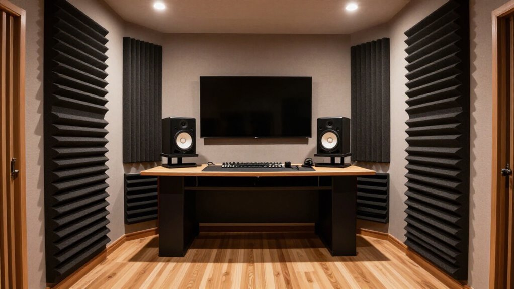
Put bass traps first in the trihedral corners, where two walls meet the floor or ceiling, because modal pressure commonly peaks at these three-surface junctions.
Prioritize full-height front and rear corners, then treat remaining wall-to-wall corners based on measurements.
Use 6-inch-or-deeper porous traps, ideally straddling corners with an air gap, or tuned membrane traps for verified modes.
Keep HVAC vents clear. A consistent 40 Hz sweep will show which corners need further attention before permanent changes.
Prioritize Trihedral Room Corners
Start with trihedral corners, where two walls meet the floor or ceiling, because they influence room modes along all three dimensions. In a square or rectangular room, you have eight such locations: four floor corners and four ceiling corners. Treat these first, since their geometry couples length, width, and height modes.
Floor tri-corners can conflict with doors, furniture, traffic paths, or equipment, so ceiling corners often provide the more workable installation points. If your ceiling is 8 feet high, stack two 4-foot corner traps to cover one full-height tri-corner. This arrangement maximizes continuous treatment along the junction without consuming floor area.
After you address trihedral positions, use wall-to-wall corners as secondary locations. A rectangular room has four, affecting length, width, and some height modes.
Pressure Peaks at Three-Surface Junctions
At each tri-corner, rigid walls, floor, and ceiling constrain particle velocity, allowing modal sound pressure to accumulate at the three-surface junction. In a square or rectangular room, you have eight such locations. Because rigid boundaries force particle velocity toward zero, modal pressure peaks near them; pressure and velocity remain 90° out of phase.
This makes the junction a strategically strong region, but porous absorption still depends on particle motion within the trap. You improve coupling by spacing or angling the absorber away from its boundaries, exposing it to higher-velocity air. A tri-corner can affect length, width, and height modes simultaneously, rather than targeting only one room dimension. That interaction gives you broader low-frequency control across the modal field than a single-wall installation can provide.
Floor-to-Ceiling Corner Coverage
Because low-frequency energy accumulates along vertical room boundaries, floor-to-ceiling traps in the front and rear wall-to-wall corners provide broad modal coverage. In a rectangular room, this placement intercepts bass buildup over a greater vertical extent than short, isolated sections. With a standard 8-foot ceiling, you can stack two 4-foot corner traps to treat the full height of each selected corner.
That continuous coverage also addresses the adjacent tri-corners, where two walls meet the floor or ceiling. These junctions influence resonances associated with room length, width, and height, so extending treatment across both ends can improve response throughout the listening area. If budget or space prevents complete treatment, measure the room or listen for persistent peaks, then prioritize the floor-to-ceiling corners showing the strongest buildup.
Broadband and Membrane Traps
You’ll get the best low-frequency performance from broadband porous traps by using thicker panels and corner air gaps, since 3-inch panels lose effectiveness near 250 Hz. You should place membrane traps at high-pressure locations for their tuned frequency, rather than assuming they belong where porous traps work best. Match each trap type to the modal frequency range and its pressure-velocity distribution.
Broadband Trap Performance
Broadband porous traps absorb through friction as moving air passes through mineral wool or fiberglass, so their placement should favor locations with high particle velocity rather than pressure peaks. Because modal pressure and velocity remain 90° out of phase, you’ll generally gain more from corners when you straddle them, creating an air gap behind the material.
That offset moves the absorber away from boundary pressure maxima and improves low-frequency reach. Use at least 6-inch fiberglass where space permits; thin panels can weaken near 250 Hz. Compare placement variables in practice:
| Trap build | Position | Expected result |
|---|---|---|
| 2-inch panel | Flat wall | Limited below 250 Hz |
| 6-inch panel | Straddled corner | Deeper absorption |
| 6-inch panel | Air-gapped corner | Improved low bass |
| Thick porous trap | High-velocity zone | Broadest broadband control |
Membrane Trap Tuning
Membrane traps target low-frequency pressure maxima rather than the high-velocity zones that favor porous absorbers, so their placement must match both the room mode and the trap’s tuning frequency. You should identify the mode you need to control, then locate its pressure maximum before installing the absorber. A resonant design works by converting pressure-driven panel motion into loss, so a mistuned unit or an incorrect location delivers limited benefit.
Rigid- and limp-mass panels, sealed-box units, and free-hanging designs use this principle. They can supplement porous treatment when conventional panels lose low-end effectiveness. Because room modes can produce peaks and nulls exceeding 20 dB below roughly 300 Hz, measurement should confirm both the modal problem and the trap’s operating band before you commit to a permanent installation.
Placement By Frequency Range
Placement depends on both absorber type and the frequency range you need to control. Use broadband porous traps in corners: an angled panel stands away from both walls, increasing its effective depth toward the quarter-wavelength requirement at lower frequencies. Choose 6-inch-or-thicker porous traps and add an air gap where practical; typical 3-inch fiberglass panels lose effectiveness near 250 Hz. Since many modal problems lie below 150 Hz, substantial corner treatment matters.
| Trap type | Frequency focus | Placement rule |
|---|---|---|
| 3-inch porous | Above ~250 Hz | Corners help, but depth limits bass control |
| 6-inch porous | Lower bass | Straddle corners; retain an air gap |
| Membrane | Tuned frequency | Locate its pressure maximum |
Map the target mode’s pressure distribution first. They’re resonant pressure absorbers; outside its maximum, they may contribute little.
Room Dimensions and Modal Frequencies
Your room’s length, width, and height set axial modal frequencies, with each dimension producing standing-wave resonances below roughly 300 Hz. You can estimate a mode with (f = c/(2d)), then calculate its harmonics to map likely pressure peaks and nulls. Measure or listen for ringing and response swings, often 20 dB or more, to identify the frequencies and corners that need the most treatment.
How Dimensions Set Modes
Room dimensions determine where low-frequency modes form: each pair of parallel boundaries supports standing waves along its length, width, or height. Those boundary pairs create distinct modal patterns, so your room’s proportions govern bass reinforcement and cancellation at listening and source positions. Modes, standing waves, eigentones, or modal resonances, can produce peaks and nulls exceeding 20 dB.
They dominate much of distortion below 300 Hz in rooms; many serious problems occur below 150 Hz. Relate trap placement to dimensions involved. Wall-to-wall corner traps interact with length and width modes and can influence some height modes. Tri-corner traps couple to pressure maxima created across all three dimensions. If you place absorption on a side wall, you primarily address width-related modal energy, not every low-frequency imbalance.
Calculating Modal Frequencies
You can predict a rectangular room’s modal frequencies from its length, width, and height. Use f₍nx,ny,nz₎ = c/2√[(nx/L)² + (ny/W)² + (nz/H)²], with c ≈ 343 m/s and nonnegative indices that aren’t all zero. This equation covers every mode family.
| Dimension | Formula | First three modes (5 m) |
|---|---|---|
| Any axis | f_n = n·343/(2D) | 34, 69, 103 Hz |
For each dimension, calculate axial modes directly; only one index is nonzero. Tangential modes use two nonzero indices, while oblique modes use three. Below roughly 300 Hz, these frequencies strongly shape low-frequency behavior. Similar dimensions cluster modes; varied dimensions spread them more evenly. Use measured internal dimensions, since small errors shift the calculated results. Don’t round dimensions prematurely during calculations.
Identifying Problem Frequencies
Problem frequencies emerge where your room’s dimensions create closely spaced or strongly excited modal resonances. These standing waves, also called room modes, occur at dimension-dependent frequencies and can produce response peaks and nulls exceeding 20 dB below roughly 300 Hz. Focus first below 150 Hz: modes are relatively sparse there, so individual resonances often dominate what you hear.
A mode stores energy and decays slowly, causing boom, extended ringing, or a one-note bass character. Compare your calculated modal frequencies with measurement data and listening results to identify persistent peaks, deep dips, and slow decay. Then match treatment to the affected dimensions. Wall-to-wall corner traps primarily address modes tied to room length and width. Tri-corner traps can influence modal behavior along length, width, and height.
Stack 24-Inch Corner Panels
Stack two 24-inch corner panels vertically to create a 4-foot bass-trapping section. This arrangement increases coverage along the corner, where low-frequency pressure commonly accumulates. In an 8-foot-high room, install two stacked sections end to end to span from floor to ceiling. Use a wall-to-wall corner when you need to address modes associated primarily with room length and width. Use a tri-corner when you want the treatment to influence modal behavior across length, width, and height.
If your panel inventory is limited, don’t assume every corner contributes equally. Play a consistent low-frequency test signal, then compare corner levels by ear or with an SPL meter. Place the stacks where measurements or listening reveal the strongest bass buildup, and verify locations target the identified frequencies directly.
Avoid Blocking HVAC Vents
Before installing a bass trap in any corner, inspect the adjoining walls, floor, and ceiling for HVAC supply or return vents. A trap that covers a register restricts designed air movement, so don’t treat acoustic placement as more important than ventilation performance. Check the trap’s full footprint, including its thickness and mounting clearance, against each vent’s discharge or intake path.
If a corner vent conflicts with the installation, select another corner that still targets strong low-frequency pressure buildup. A rectangular room provides 12 corners, giving you alternatives without compromising airflow. You can also change the trap configuration or use a nearby unobstructed corner. Keep supply air distribution and return air capture clear; restricted airflow can reduce HVAC efficiency and create uneven room conditions.
Foam Panels Aren’t Bass Traps
Thin acoustic foam panels won’t control the low-frequency room modes that cause boomy, uneven bass. Their thin, porous structure primarily absorbs midrange and treble energy, so treating walls with foam can make your room sound dull while leaving its bass response largely unchanged.
- Foam mainly targets mid and high frequencies.
- Many problematic modes occur below 150 Hz.
- Even 3-inch fiberglass panels lose effectiveness near 250 Hz.
- Low-frequency absorption requires depth, airspace, or resonance.
- Use mineral-wool, fiberglass, or tuned traps for bass.
Porous bass traps work by resisting air-particle motion inside dense material; thickness places that material where low-frequency particle velocity is useful. You shouldn’t substitute foam for purpose-built corner traps. Specify deep porous treatment or a tuned resonant design when measurements show modal buildup.
Run a 40 Hz Sweep
Once you’ve chosen purpose-built bass trapping, run a consistent 40 Hz tone or sweep and walk the room to identify where modal buildup is strongest. Keep the playback level, source position, and measurement method unchanged throughout the test, or your comparisons won’t be reliable. Check vertical wall corners, wall-to-floor junctions, and wall-to-ceiling junctions; 40 Hz pressure maxima can vary substantially between apparently similar locations.
Listen for increased loudness, but verify it with Room EQ Wizard or a handheld SPL meter. Record the level at each candidate position. Higher readings indicate stronger modal buildup and identify the corners that deserve treatment first. If your budget or space limits trap quantity, install traps at the highest-reading corners before treating locations with lower energy. Repeat the test after installation to confirm reduction.
Conclusion
Start with your trihedral corners, where three surfaces create the strongest low-frequency pressure peaks. Extend treatment from floor to ceiling, using stacked 24-inch broadband or membrane traps sized for your room’s modal range. Don’t obstruct HVAC vents, and don’t mistake thin foam for bass control. After installation, run a 40 Hz sweep and measure decay, nulls, and peaks. You’ll get the largest improvement by treating corners first, then refining placement from measurements in your room.